

Radar apparatus
a technology of radar and circuit size, applied in the field of radar equipment, can solve the problems that the conventional mimo radar may suffer from an increase in circuit size, and achieve the effect of reducing circuit siz
- Summary
- Abstract
- Description
- Claims
- Application Information
AI Technical Summary
Benefits of technology
Problems solved by technology
Method used
Image

Examples
embodiment 1
Configuration of Radar Apparatus
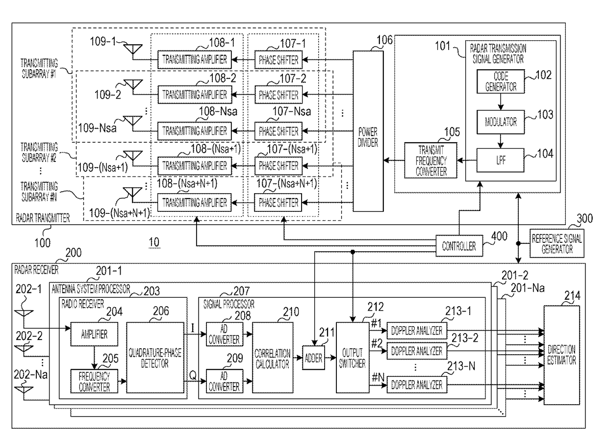
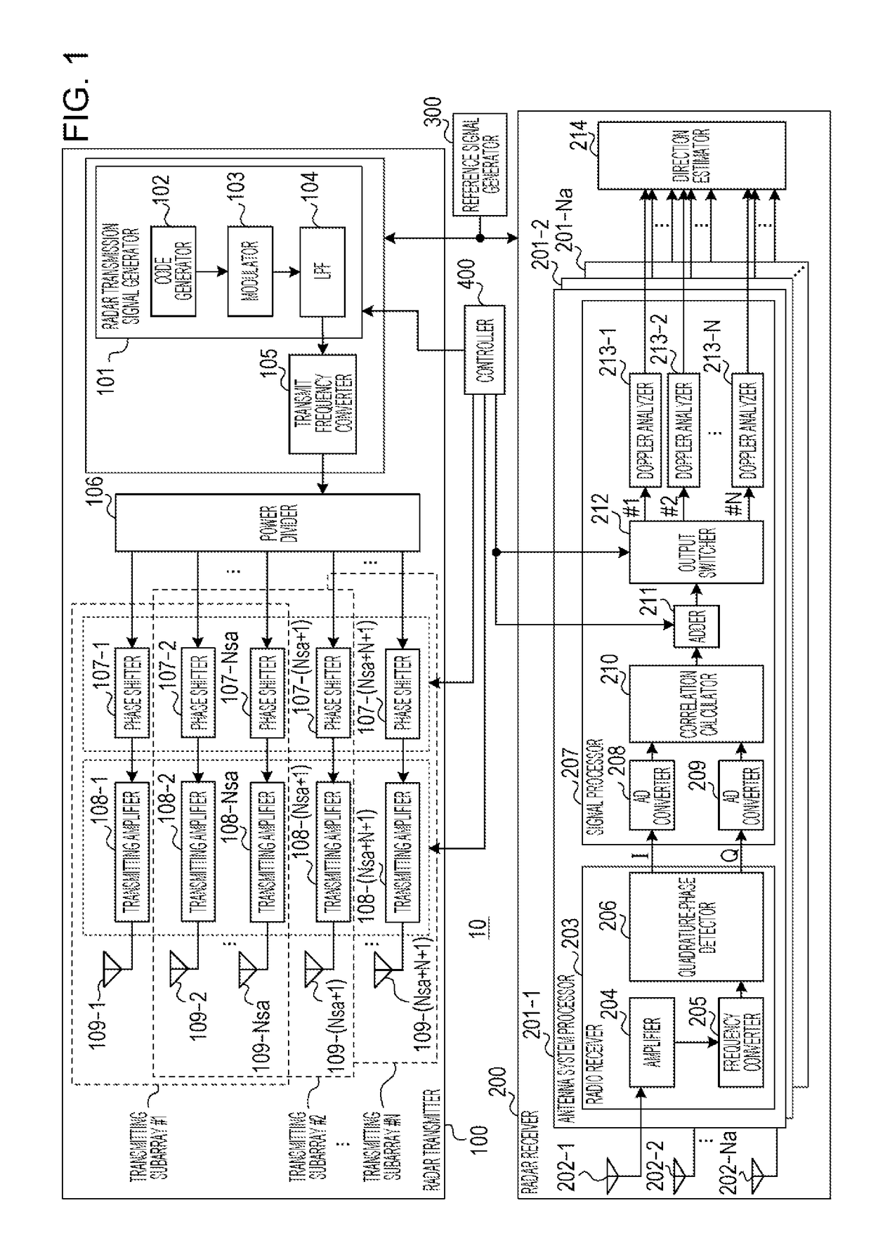
[0062]FIG. 1 is a block diagram showing a configuration of a radar apparatus 10 according to Embodiment 1.
[0063]The radar apparatus 10 includes a radar transmitter (transmitting branch) 100, a radar receiver (receiving branch) 200, a reference signal generator 300, and a controller 400.
[0064]The radar transmitter 100 generates radio-frequency radar signals (radar transmission signals) in accordance with reference signals received from the reference signal generator 300. Then, the radar transmitter 100 transmits the radar transmission signals while switching among a plurality of transmitting subarrays #1 to #N in a time-division manner. Note here that N is an integer of not less than 2.
[0065]The radar receiver 200 receives, through a receiving array antenna including a plurality of receiving antennas 202-1 to 202-Na, reflected-wave signals produced by the radar transmission signals being reflected by a target (not illustrated). The radar receiver 200 p...
embodiment 2
[0177]Those components of a radar apparatus according to Embodiment 2 which are identical to those of the radar apparatus 10 according to Embodiment 1 are described with reference to FIG. 1.
[0178]Embodiment 2 describes a configuration in which receiving antennas 202 are not only arranged in a predetermined direction (e.g. a horizontal direction) but also arranged with a displacement in a direction (vertical direction) perpendicular to the predetermined direction. This antenna arrangement enables the radar apparatus 10 to form a direction-of-arrival estimation both in the horizontal direction and in the elevation angle direction.
Example Antenna Arrangement 5
[0179]FIGS. 11A to 11C show examples of an arrangement of transmitting subarrays, an arrangement of receiving antennas 202, and an arrangement of a virtual receiving array, respectively, in Example Antenna Arrangement 5.
[0180]Example Antenna Arrangement 5 shows an antenna arrangement in which the number N of transmitting subarrays...
embodiment 3
[0230]Those components of a radar apparatus according to Embodiment 3 which are identical to those of the radar apparatus 10 according to Embodiment 1 are described with reference to FIG. 1.
[0231]It should be noted that Embodiment 3 is similar to Embodiments 1 and 2 in that adjacent transmitting subarrays are provided so as to share at least one transmitting antenna 109 with each other.
Example Antenna Arrangement 7
[0232]In Example Antenna Arrangement 1, the receiving antennas 202 are placed at regular spacings in a predetermined direction (e.g. a horizontal direction). Meanwhile, in Example Antenna Arrangement 7, the receiving antennas 202 are placed at irregular spacings in a predetermined direction.
[0233]FIGS. 17A to 17C show examples of an arrangement of transmitting subarrays, an arrangement of receiving antennas 202, and an arrangement of a virtual receiving array, respectively, in Example Antenna Arrangement 7.
[0234]Example Antenna Arrangement 7 shows an antenna arrangement in...
PUM
 Abstract
Description
Claims
Application Information