Projector and image display method

a projector and image technology, applied in the field of projectors and image display methods, can solve the problems of periodic replacement of lamp light sources and relatively short life of lamp light sources

Active Publication Date: 2018-04-05
SHARP NEC DISPLAY SOLUTIONS LTD
View PDF1 Cites 8 Cited by
  • Summary
  • Abstract
  • Description
  • Claims
  • Application Information

AI Technical Summary

Benefits of technology

[0026]An image display method according to the present invention causes a first light containing a first fluorescence generated in a first fluorescence region to be output from a first light source;

Problems solved by technology

However, the lamp light source has a relatively short life and needs periodic replacement.

Method used


Image

  • Projector and image display method
  • Projector and image display method
  • Projector and image display method

Examples


first example embodiment

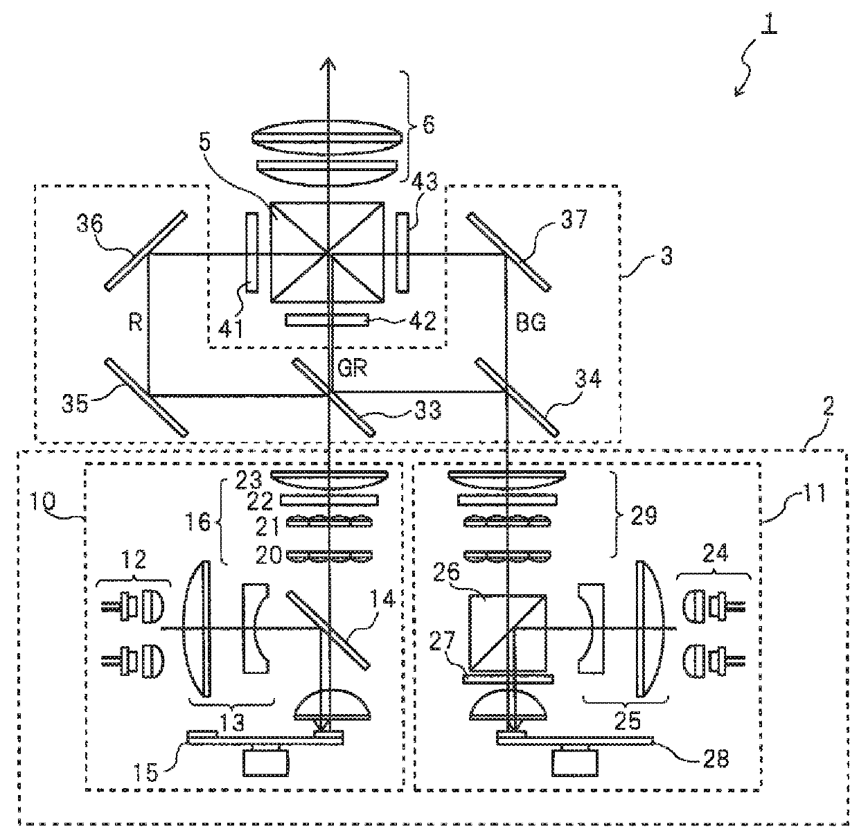
[0053]FIG. 2 is a schematic view for explaining configuration of an essential part of a first example embodiment of a projector according to the present invention.

[0054]By referring to FIG. 2, projector 1 includes light source part 2, light separation optical system 3, display elements 41, 42, and 43, color synthesizing element 5, and projection optical system 6. In the projector, an image generating part which receives a video signal and causes display elements 41, 42, and 43 to perform display, a power source part, a cooling part and the like are provided in addition to the aforementioned optical system, but only an essential part of the optical system is illustrated in FIG. 2.

[0055](Light Source Part)

[0056]Light source part 2 is constituted by first light source 10 and second light source 11.

[0057](First Light Source)

[0058]First light source 10 includes laser light source 12, lens group 13, dichroic mirror 14, fluorescent body wheel 15, and illumination optical system 16. Other t...

second example embodiment

[0104]Subsequently, a second example embodiment according to the present invention will be explained.

[0105]FIG. 6 is a schematic view for explaining configuration of an essential part of an optical system of the second example embodiment of the projector according to the present invention.

[0106]In projector 601 of this example embodiment, laser light source 24 that outputs the blue excitation light in projector 1 illustrated in FIG. 2 is made laser light source 624 generating a blue-purple excitation light with a wavelength of 405 nm, dichroic mirror 626 is arranged instead of prism 26 and wavelength plate 27, and fluorescent body wheel 28 is made fluorescent body wheel 628 on which yellow fluorescent body 632a and blue fluorescent body 632b are formed, respectively, as illustrated in FIG. 7. Since other configurations are the same as projector 1 illustrated in FIG. 2, the same reference numerals as those in FIG. 2 are given, and the explanation will be omitted.

[0107]In this example...

third example embodiment

[0110]Subsequently, a third example embodiment according to the present invention will be explained.

[0111]In both the first example embodiment illustrated in FIG. 2 and the second example embodiment illustrated in FIG. 6, the fluorescent body and the reflection plate provided in the annular region irradiated with the excitation light are formed by two segments equally dividing the ring and as a result, in both the first example embodiment and the second example embodiment, the generated sub frames are two sub frames having equal periods.

[0112]In this example embodiment, as illustrated in a plan view in FIG. 8, an annular region of fluorescent wheel 801 provided on the second light source irradiated with an excitation light is equally divided into regions 8001 to 800n. In regions 8001 to 800n, a yellow fluorescent body and a reflection plate are provided alternately. Since an optical system in this example embodiment is similar to that in the first example embodiment, the explanation...


PUM


Abstract

The present invention provides a projector with high brightness, the projector including: a first light source that outputs a first light containing a first fluorescence generated in a first fluorescence region; a second light source that outputs a second light containing a second fluorescence generated in a second fluorescence region; first to third image display elements; a light separation optical system that generates an illumination light illuminating the first to third image display elements with colors different from each other from the input first light and second light and radiates the illumination light to the first to third image display elements; and a controller that causes the first to third image display elements to display an image according to an input video signal and colors of the illumination light radiated to the first to third image display elements.

Description

TECHNICAL FIELD[0001]The present invention relates to a projector and an image display method.BACKGROUND ART[0002]Conventionally, a high-pressure mercury lamp and the like have been used as a light source of a projector. However, the lamp light source has a relatively short life and needs periodic replacement.[0003]Thus, as a light source replacing the lamp light source, a projector having a light source using a fluorescent body is proposed.[0004]Patent Literature 1 (JP2012-123179A) discloses a projector having a laser light source and a light source using a fluorescent body.[0005]Projector 1 shown in FIG. 1 of Patent Literature 1 includes light source device 2, color separation optical system 3, liquid crystal light bulbs 4R, 4G, and 4B, color synthesizing element 5, and projection optical system 6. Light source 2 includes laser light source 9, dichroic mirror 10, ¼ wavelength plate 11, fluorescent body wheel 12, collimate optical system 13, lens arrays 14 and 15, polarization conv...

Claims


Application Information

Patent Timeline
Patent Type & Authority Applications(United States)
IPC IPC(8): G03B21/20G03B21/00
CPCG03B21/2073G03B21/006G03B21/2013G03B21/204G03B33/12
Inventor ISHIKAWA, TAKASHI
Owner SHARP NEC DISPLAY SOLUTIONS LTD
Why Eureka
Try Eureka