Method for producing drilled cooling holes in a gas turbine engine component

a gas turbine engine and cooling hole technology, applied in process and machine control, process control, instruments, etc., can solve problems such as lack of consistency accuracy of holes, laser burns on the opposite wall, and deviations

Active Publication Date: 2018-04-12
XIAMEN UNIV
View PDF26 Cites 21 Cited by
  • Summary
  • Abstract
  • Description
  • Claims
  • Application Information

AI Technical Summary

Problems solved by technology

Development in cooling technique resulted in complicated cooling scheme, multiple (104-106) fine-shaped holes (0.3-1.2 mm) with divergent oblique angles (10°-75°) exist on such air-cooled components in which cooling air flows through the airfoil and discharged through cooling holes.
Firstly it is because the actual wall thickness at the designed location of drilled holes deviates from the ideal wall thickness due to the that the components such as gas turbine blades with intricate geometry and tight tolerances are often fabricated by investment casting, which is a multiplex nonlinear physical processes coupled with geometry, material properties and boundary conditions.
Furthermore, the deviation may occur when clamping the component in the machining process, including the movement and deformation of the component, etc.
As is apparent from the deviations of the ideal drilled holes features discussed above regarding the geometries and positions of drilled hole, the defects such as the occurrence of blind holes, laser burns on the opposite wall, as well as the lack of consistency accuracy of holes.
Although these documents teach various methods for producing drilled hole or drilled holes in a gas turbine blade, or the like, there is no intent to establish, or knowledge about the method for producing drilled holes parametrically in a gas turbine engine component with accurate geometrical and positional values with the consideration of the deviations generated before and after machining.

Method used


Image

  • Method for producing drilled cooling holes in a gas turbine engine component
  • Method for producing drilled cooling holes in a gas turbine engine component
  • Method for producing drilled cooling holes in a gas turbine engine component

Examples


Embodiment Construction

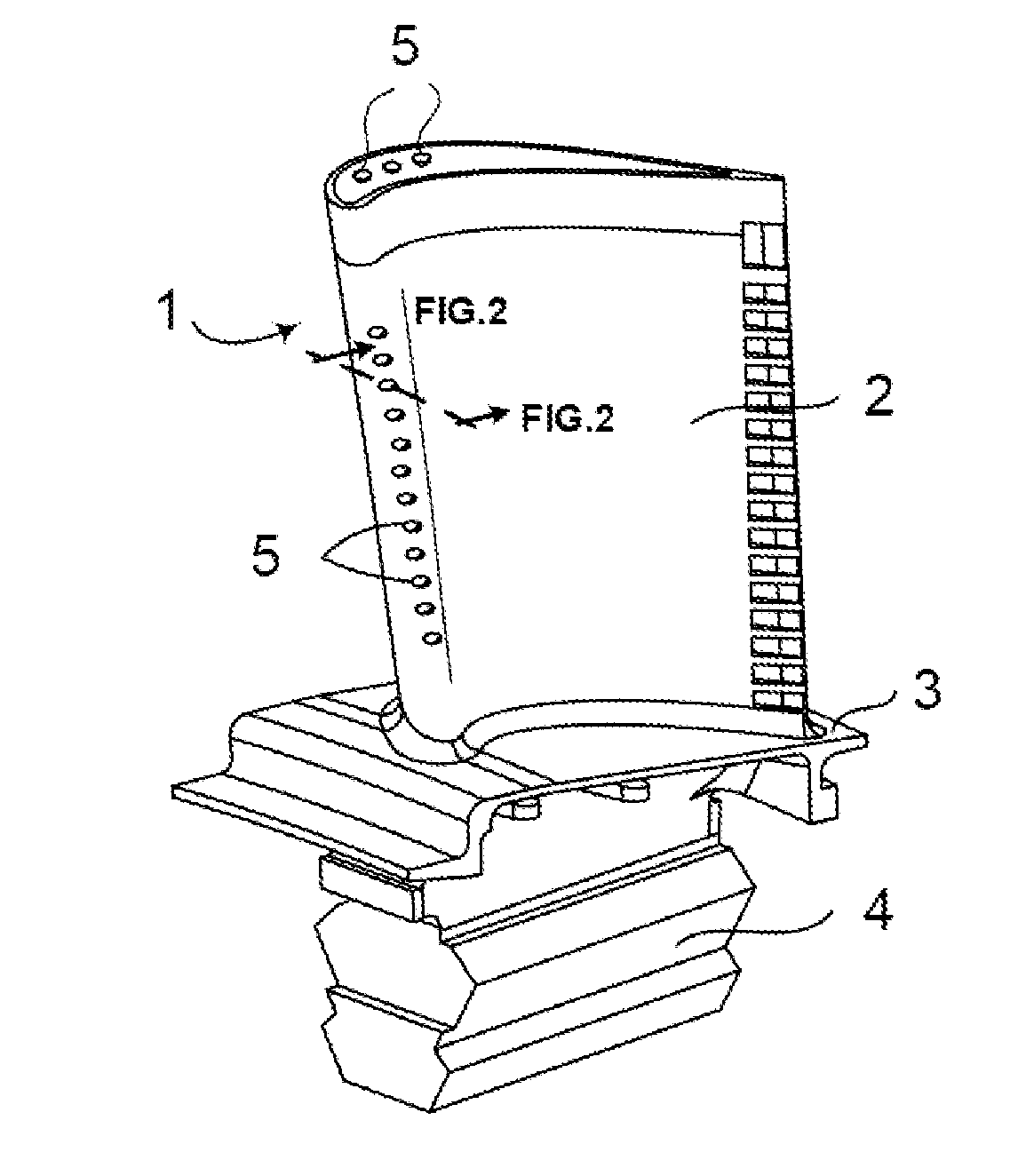
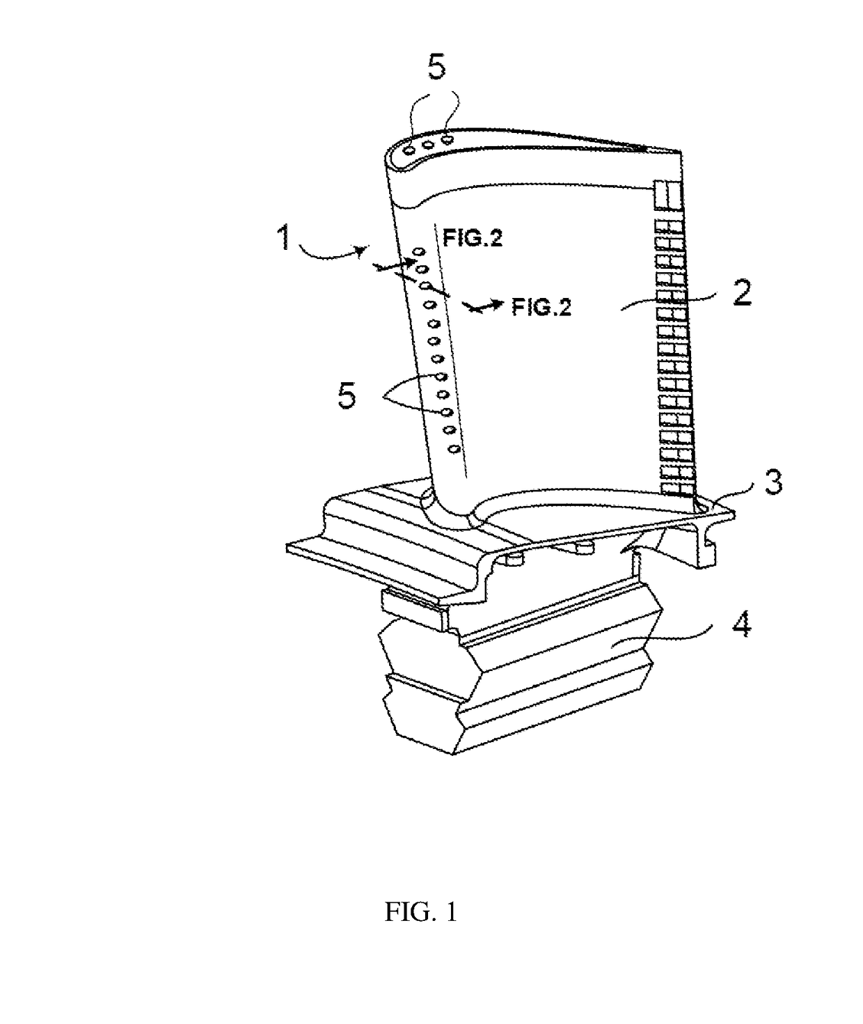
[0024]The present invention will be described in reference to a high pressure gas turbine blade [1] illustrated in FIG. 1 typically formed of a nickel-based super-alloy. The high pressure gas turbine blade [1] includes an airfoil section [2] and a blade platform [3], which are encounter the hot combustion gases. The cooling holes [5] need to be developed on the airfoil section [2] so as to attempt to cover the high pressure gas turbine blade [1] that is to be cooled and in its way shield them from the hot gas. The airfoil section [2] and the blade platform [3] are anchored to a turbine disk (not shown) with a blade tenon [4] formed on a root section of the high pressure gas turbine blade [1]. Since the effectiveness of the cooling depends significantly on the geometrical and positional values of the drilled holes, which means the cooling holes [5] on airfoil section [2] need to be straight, accurate, and exactly positioned. The cooling holes [5] may be produced by various well-devel...


PUM

PropertyMeasurementUnit
displacementaaaaaaaaaa
ultrasonicaaaaaaaaaa
heightaaaaaaaaaa

Abstract

A method for accurately producing the drilled hole in a wall of a component fabricated by investment casting process, such as for use in a blade or steam turbine includes the following steps. The 3D data of actual component is obtained from the measurements or from the numerical simulation. The actual model and the ideal model are aligned and compared, a series of cutting planes are given to establish a series of 2D cross-sections of the actual and ideal models after registration. Each cross-section is dispersed into discrete points, the distance between each corresponding points are calculated and formed into 2D displacement. The accurate parametric model consisting of the depth, hole center, and the nominal vector is obtained on the basis of considering the deviations in geometrical and positional values. The drilled hole is then produced according to the corrected parametric drilled-hole geometrical and positional value.

Description

CROSS REFERENCE TO RELATED APPLICATIONS[0001]This non-provisional application claims the benefit under 35 U.S.C. § 119(e) to U.S. Provisional Application No. 62 / 404,877 filed in the United States on Oct. 6, 2016, the entire contents of which are hereby incorporated by reference.FIELD OF THE INVENTION[0002]The present invention relates to a method for producing the drilled holes with accurate geometrical and positional parameters of an air-cooled components, in particular for the production of film cooling holes with accurate geometrical and positional values in a blade of a gas or steam turbine. Preferably in an aero-engine hollow turbine blade with multiple drilled holes introduced to ensure proper cooling air flow through the cooling holes.BACKGROUND OF THE INVENTION[0003]To achieve high levels of efficiency with a high output at the same time, gas turbines are operated with an extremely inlet temperature, which often exceeds the permissible material temperature of turbine blading...

Claims


Application Information

Patent Timeline
Patent Type & Authority Applications(United States)
IPC IPC(8): B23K26/382B23K26/384B21D53/78B23H9/10F01D5/18
CPCB23K26/389B23K26/384B21D53/78B23H9/10F01D5/186B23P2700/06F05B2200/11F05B2220/302F05B2230/103F05B2250/29F05B2260/202B23H9/14F01D21/003G05B19/041
Inventor DONG, YIWEIYOU, YANCHENGYIN, CHUNPINGLI, XIAOJIZHAO, QIWANG, ERTAIWU, ZONGPU
Owner XIAMEN UNIV
Why Eureka
Try Eureka