
Strain measurement sensor capable of indicating strain with color emission and method of manufacturing the same

a sensor and color emission technology, applied in the field of strain measurement sensors, can solve the problems of inability to realize exact red color emission of such a material, inability to meet the requirements of strain sensing of strain sensors operating through expensive equipment, and difficulty in finding a light conversion material capable of converting green emission to red emission among the entire inorganic phosphor group

Active Publication Date: 2018-04-26
KYUNGPOOK NAT UNIV IND ACADEMIC COOP FOUND
View PDF7 Cites 7 Cited by
  • Summary
  • Abstract
  • Description
  • Claims
  • Application Information

AI Technical Summary

Benefits of technology

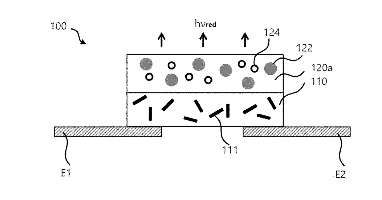
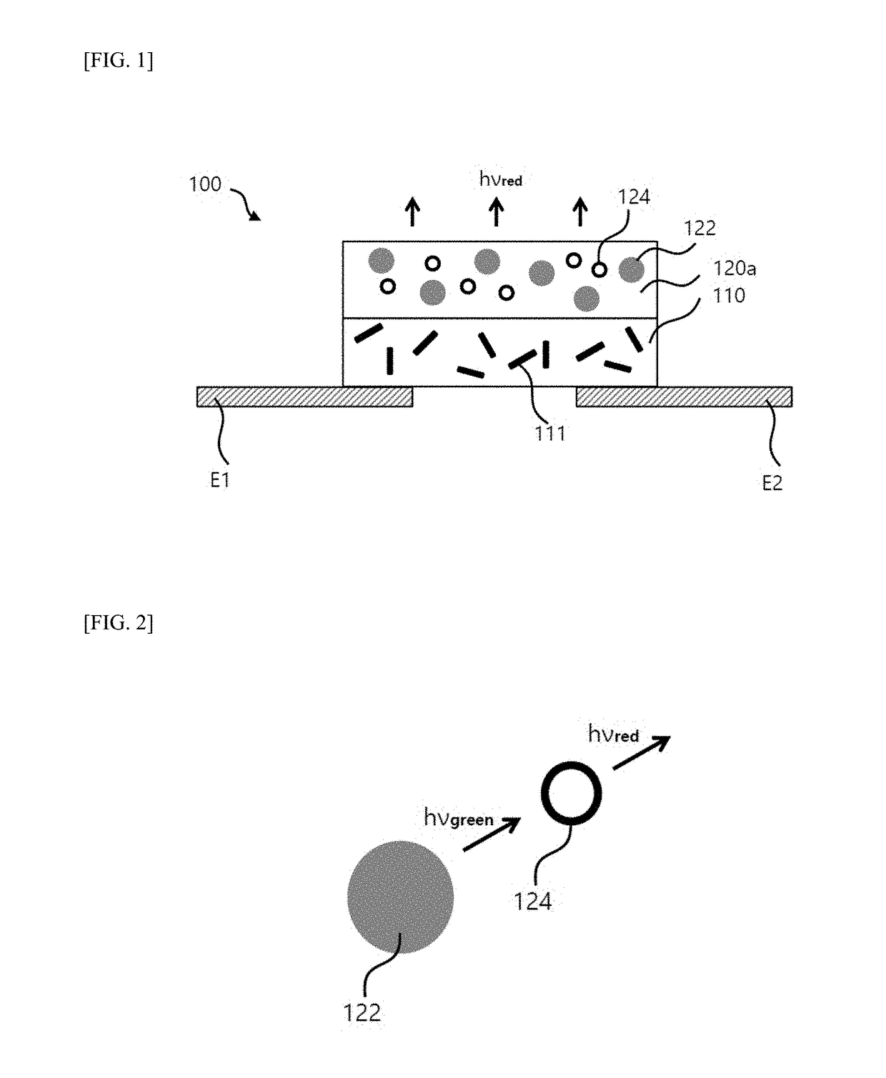
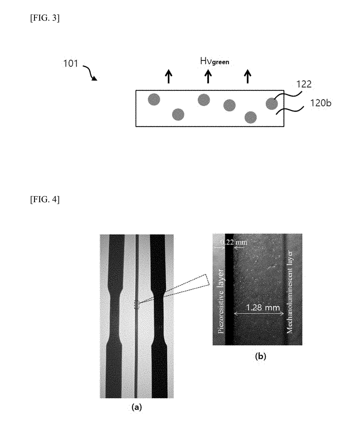
The present patent describes a strain measuring sensor that can indicate a strain with color emission. The sensor includes a piezoresistive layer and a mechano-luminescent layer. The mechano-luminescent layer includes green emissive particles and red emissive particles, which absorb and convert the green emission to red emission. The intensity of the red emission is proportional to the strain rate. The sensor can be used for safety-related applications and biomedical applications. The method of manufacturing the sensor involves curing the mechano-luminescent layer and the piezoresistive layer simultaneously.

Problems solved by technology

However, strain sensors operating through expensive equipment cannot meet requirements for strain sensing in the field.
However, this is true only when conventional trap emission mechano-luminance mechanism responding to a stress is applied for rigid matrix materials such as epoxy resin containing the compounds.
Although the friction organic electroluminescent material exhibiting yellow emission such as ZnS based compounds has been developed, it is impossible to realize exact red color emission by such a material.
In addition, there is a limit in that it is difficult to find a light conversion material capable of converting green emission to red emission among the entire inorganic phosphor group.
Thus, this may lead to an increase in a bonding force between the piezoresistive layer and mechano-luminescent layer.

Method used


Image

  • Strain measurement sensor capable of indicating strain with color emission and method of manufacturing the same
  • Strain measurement sensor capable of indicating strain with color emission and method of manufacturing the same
  • Strain measurement sensor capable of indicating strain with color emission and method of manufacturing the same

Examples


example 1

[0076]A strain measuring sensor in this example has been manufactured as follows:

[0077]ZnS:Cu (available from LONCO Company Limited), rhodamine B (available from Sigma-Aldrich), silica (SiO2, available from Sigma-Aldrich), carbon nanotube (CNT, available from carbon nano material Technology Co. Ltd) and PDMS (poly dimethyl siloxane, Sylgard® 184 Silicone Elastomer) are prepared. In this connection, the radius of the silica was 20 nm, and the multi-wall CNT with a radius of 20 nm and a length of 5 μm was used.

[0078](1) Preparation for Material for Mechano-Luminescent Layer

[0079]First, in order to coat the silica surface with rhodamine B, 0.1 g of rhodamine B and 10 g of silica were mixed with 200 mL of methanol and then continuously stirred at 50° C. using a magnetic stirrer. Then, the methanol was completely evaporated, such that the silica coated with the rhodamine B (silica@rhodamine B) as red powders was obtained.

[0080]Then, the silica@rhodamine B and ZnS:Cu were homogeneously mi...

example 2

[0088]The example 2 was different from the example 1 in that, for producing the mechano-luminescent layer, only ZnS:Cu was employed.

[0089]Characteristics Evaluation—1: Optical Characteristics

[0090]Six wavelengths in the range of 254 nm to 365 nm were applied to each of the mechano-luminescent layer made according to the example 1, the mechano-luminescent layer made according to the example 2 and the red emission layer for comparison respectively. Then, emission intensities emitted from the mechano-luminescent layer made according to the example 1, the mechano-luminescent layer made according to the example 2 and the red emission layer for comparison were measured respectively. The results are shown in FIG. 5.

[0091]In FIG. 5. FIG. 5(a) indicates a photoluminescence (PL) spectrum of the mechano-luminescent layer according to the example 1, and FIG. 5(b) indicates emission spectrums of the mechano-luminescent layer according to the example 2 and the red emission layer for comparison. I...


PUM


Abstract

A strain sensor with color emission indicating a strain is disclosed. The strain sensor can include a piezoresistive layer having a first portion of a polymer matrix body and conductive fillers dispersed in the first portion of the polymer matrix body, a mechano-luminescent layer having a second portion, which is disposed on the first portion, of the polymer matrix body, green emissive particles, and red emissive particles, the green and red emissive particles being dispersed in the second portion of the polymer matrix body, and a first and second electrodes spaced apart from each other and directly connected to the piezoresistive layer.

Description

CROSS-REFERENCE TO RELATED APPLICATION[0001]This application claims the benefit under 35 U.S.C. § 119(a) of Korean Patent Application No. 10-2016-0137640 filed on Oct. 21, 2016, in the Korean Intellectual Property Office, the entire disclosure of which is incorporated herein by reference for all purposes.BACKGROUND1. Field[0002]The following description relates to a strain measurement sensor capable of indicating a strain with color emission and a method of manufacturing the same, and, more particularly, to a strain measurement sensor capable of indicating a strain wherein a strain is indicated with a red or green color, and a method of manufacturing the same.2. Description of Related Art[0003]Various strain or stress sensing systems include laser photoelasticity, laser ultrasonic, Raman spectroscopy, electrical resistance measurement, and strain gauge or wire attachment techniques. However, strain sensors operating through expensive equipment cannot meet requirements for strain sen...

Claims


Application Information

Patent Timeline
IPC IPC(8): G01L1/24G01L1/18G02F1/01G02F1/00
CPCG01L1/24G02F1/0072G02F1/0128G01L1/18G01B7/18G01D7/005H10N30/30
Inventor KIM, JI SIKSOHN, KEE-SUNTIMILSINA, SUMAN
Owner KYUNGPOOK NAT UNIV IND ACADEMIC COOP FOUND
Learn More