Mechanoluminescence material and process for producing the same

a technology of mechanoluminescence and material, applied in the direction of luminescent compositions, lighting and heating apparatus, and light emission, etc., can solve the problems of limited application field, limited range of matrix materials to be used, and no investigation of material capable of emitting ligh

Inactive Publication Date: 2007-08-21
NAT INST OF ADVANCED IND SCI & TECH
View PDF15 Cites 4 Cited by
  • Summary
  • Abstract
  • Description
  • Claims
  • Application Information

AI Technical Summary

Benefits of technology

[0005]The present invention has been completed under these circumstances with an object to accomplish, by using a matrix material different from those in the conventional luminescence materials, an increase in the luminescence intensity and expansion of the application fields.

Problems solved by technology

The external stimulation to cause the phenomenon of fluorescence is usually given by ultraviolet light, electron beams, radiations such as X-rays, electric fields, chemical reactions and others but no investigations have yet been made for a material capable of emitting light when stimulated by a mechanical external force and the like.
These luminescence materials are not suitable for practical applications because of their still insufficient luminescence intensity and, in addition, the limitation of the range of the matrix materials to be used so that the application field is necessarily limited.

Method used


Image

  • Mechanoluminescence material and process for producing the same
  • Mechanoluminescence material and process for producing the same

Examples


example 1

[0028]A mechanoluminescence material was prepared by blending SrCO3, MgCO3 and Al2O3 each in a powder form having an average particle diameter of about 10 μm in a proportion corresponding to SrMgAl6O11 as the matrix material, thoroughly blending with further addition of 20% by moles of a boric acid powder (average particle diameter 10 μm) as a flux and 0.5% by moles (calculated for the metallic element) of a Eu2O3 powder to give the center of luminescence and firing the thus obtained blend at 1300° C. for 4 hours in an atmosphere of argon containing 5% by volume of hydrogen.

[0029]In the next place, a sample was prepared by pelletizing this mechanoluminescence material with an epoxy resin as a binder.

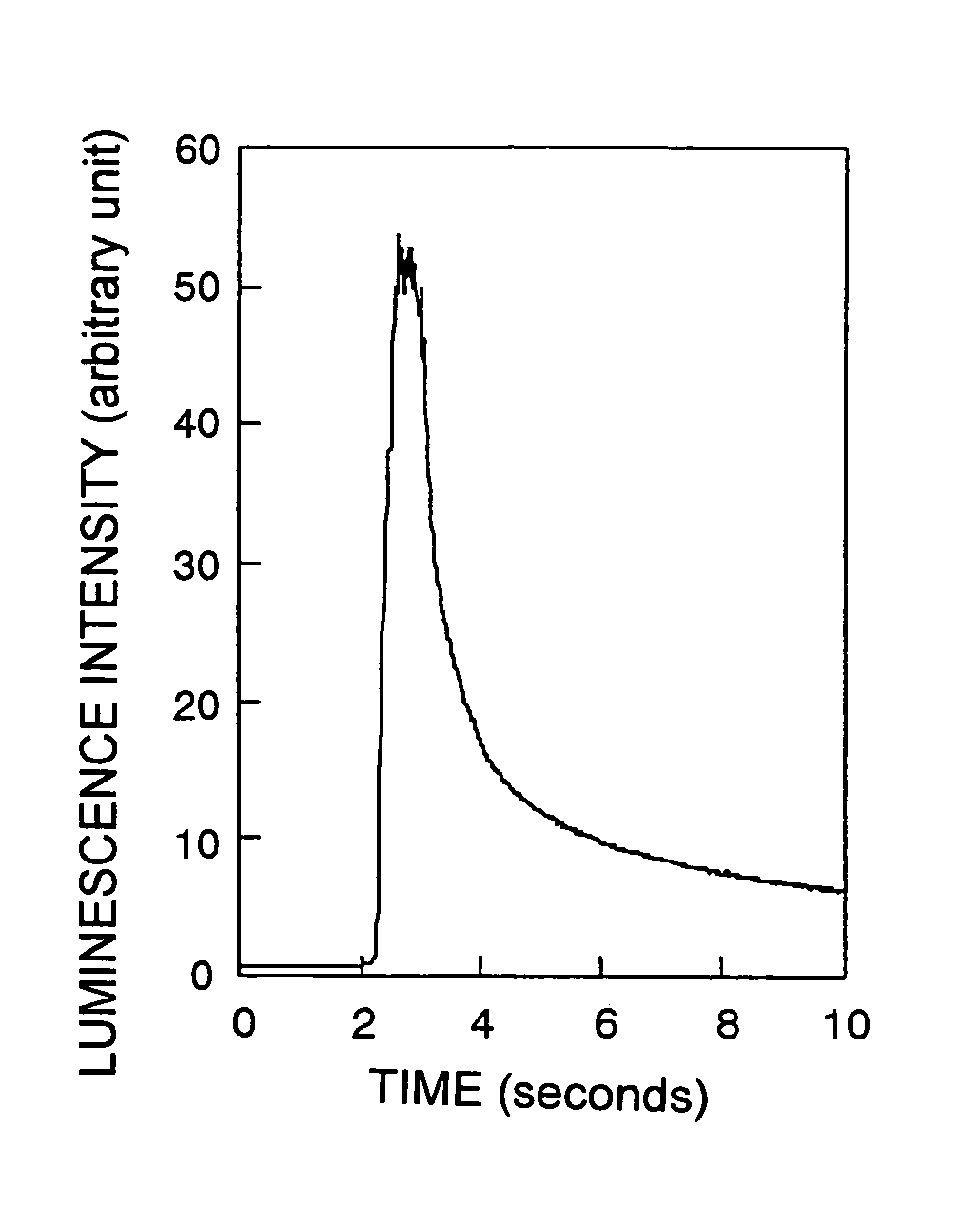
[0030]By using a vise, a mechanical action of 150 N was applied to this sample and the change with time in the luminescence intensity there is shown as a graph in FIG. 1. This sample emitted green light which was strong enough as to be clearly recognizable with naked eyes. The highest lu...

examples 2 to 4

[0034]By using the matrix materials indicated in Table 1, mechanoluminescence materials with Eu to serve as the center were prepared in the same manner as in Example 1. The highest luminescence intensities thereof were determined and the results are shown in Table 1.

[0035]

TABLE 1MatrixCenter ofluminescencematerialluminescenceintensity (cps)Example 1SrMgAl6O11Eu24990Example 2Sr2Al6O11Eu9787Example 3SrLaAl3O7Eu28694Example 4SrYAl3O7Eu4611ComparativeSrMgAl6O11None91Example

[0036]As is understood from this table, the luminescence intensity is remarkably increased by doping with a metal for the center of luminescence.


PUM

PropertyMeasurementUnit
temperatureaaaaaaaaaa
timeaaaaaaaaaa

Abstract

A mechanoluminescence material comprising a matrix of composite metal oxide containing strontium and aluminum, represented by the general formula SrM1Al6O11 (wherein M1 is an alkaline earth metal) or SrM2Al3O7 (wherein M2 is a rare earth metal), and further comprising, as luminescence centers, a metal selected from among rare earth metals and transition metals capable of emitting light when a carrier having been excited by mechanical energy returns to its ground state.

Description

TECHNOLOGICAL FIELD[0001]The present invention relates to a novel mechanoluminescence material capable of emitting light by receiving an external mechanical force as well as to a method for the preparation thereof.BACKGROUND TECHNOLOGY[0002]The phenomenon that a substance emits visible light or light in the vicinity of visible light at a low temperature, e.g., room temperature, when it receives a stimulation from outside is heretofore well known as a so-called phenomenon of fluorescence. Such a substance to cause the phenomenon of fluorescence or, namely, a phosphor, is employed for illuminating lamps such as fluorescent lamps and the like and for displays such as CRTs (cathode-ray tubes) or, namely, so-called Braun tubes, and the like.[0003]The external stimulation to cause the phenomenon of fluorescence is usually given by ultraviolet light, electron beams, radiations such as X-rays, electric fields, chemical reactions and others but no investigations have yet been made for a mate...

Claims


Application Information

Patent Timeline
Patent Type & Authority Patents(United States)
IPC IPC(8): C09K11/64C09K11/08C09K11/80C09K11/77
CPCC09K11/7734C09K11/7792F21K2/04
Inventor AKIYAMA, MORITOXU, CHAO-NANNONAKA, KAZUHIRO
Owner NAT INST OF ADVANCED IND SCI & TECH
Why Eureka
Try Eureka