Plant for waste disposal and associated method

a technology for waste disposal and waste water, applied in the field of waste water disposal plants, can solve the problems of affecting performance limits, requiring a rather complex after-treatment system, and the possibility of converting energy flows otherwise dispersed by the incinerator into further energy that can be used elsewhere, and achieves the effects of low environmental impact, high energy efficiency, and minimal environmental impa

Active Publication Date: 2018-05-03
ARCHIMEDE
View PDF0 Cites 11 Cited by
  • Summary
  • Abstract
  • Description
  • Claims
  • Application Information

AI Technical Summary

Benefits of technology

[0017]In particular, the object of the invention is to provide a plant for disposal of waste and to provide a corresponding method for disposal of waste that will enable undifferentiated treatment of organic waste of various nature and in different physical states (solid, liquid, gaseous, multiphase mixtures, etc.), irrespective of the danger of the waste itself, at the same time obtaining an extremely high energy efficiency with minimal environmental impact. In the second place, the object of the present invention is to provide a plant (and a corresponding method) in which, in addition to disposal of waste, there is envisaged a recovery of the waste itself, with an energy efficiency and a yield in terms of recovery and valorization of the waste that are extremely high with minimal environmental impact.

Problems solved by technology

In particular, for given types of waste that is dangerous for the environment and human health it is necessary to envisage separate treatment plants provided with systems for after-treatment of the reaction products that will enable release into the atmosphere of just harmless species.
A technology consolidated in the sector is that of incinerators, which, however, are affected by limits of performance due to the substantial impossibility of reaching complete and optimal combustion of the waste.
In particular, combustion of the waste in an industrial incinerator always gives rise to reaction products containing partially reacted species, notwithstanding all the measures adopted to favour exposure of the waste to the combustion air on account of the intrinsic inefficiency of this mode of waste treatment.
The result is hence a flow of reaction products that contains many dangerous species, which may require a rather complex after-treatment system (which is also characterized by operating limits, as is obvious).
In other words, the possibility of converting energy flows otherwise dispersed by the incinerator into further energy that can be used elsewhere is extremely low as compared to the amount of waste entering the incinerator.
However, this plant and the corresponding method for disposal of waste prove to be very costly from an energy standpoint in so far as there is an extremely low conversion of the energy inherent in the waste disposed of into energy that can be used elsewhere.
In particular, the process is characterized by an extremely low production of biofuels per unit mass of incoming waste, and hence is characterized by a poor yield in recovery, understood as valorization of the treated waste for production of energy and / or high-quality synthesis products (biofuels).
Furthermore, the type of waste to which the aforesaid document refers is strictly limited to depuration sludges.
This method, however, does not prevent the methane produced from being polluted by traces of other hydrocarbons and by hydrogen in amounts such as to not to enable introduction thereof into the grid.
Furthermore, the yield in terms of waste recovery—understood as the ratio between the mass flow rate of the synthesis gas at output and the mass flow rate of the waste at input—is low, as is likewise the energy efficiency of the process in terms of ratio between the lower calorific value of the output synthesis gas per unit mass of the treated waste, and the energy expended per unit input mass of the treated waste necessary for sustaining the process (consumption of traditional fossil fuel or thermal energy supplied to the system as a whole).

Method used


Image

  • Plant for waste disposal and associated method
  • Plant for waste disposal and associated method
  • Plant for waste disposal and associated method

Examples


Embodiment Construction

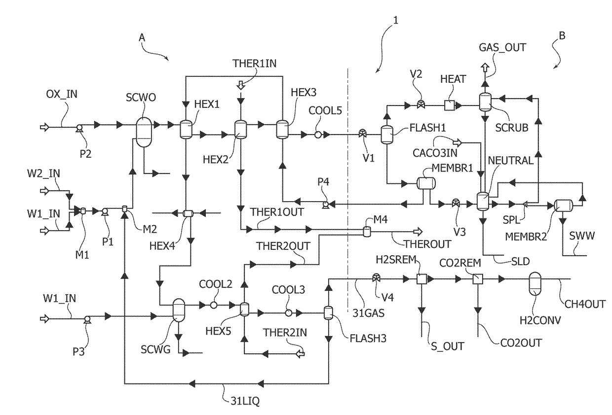
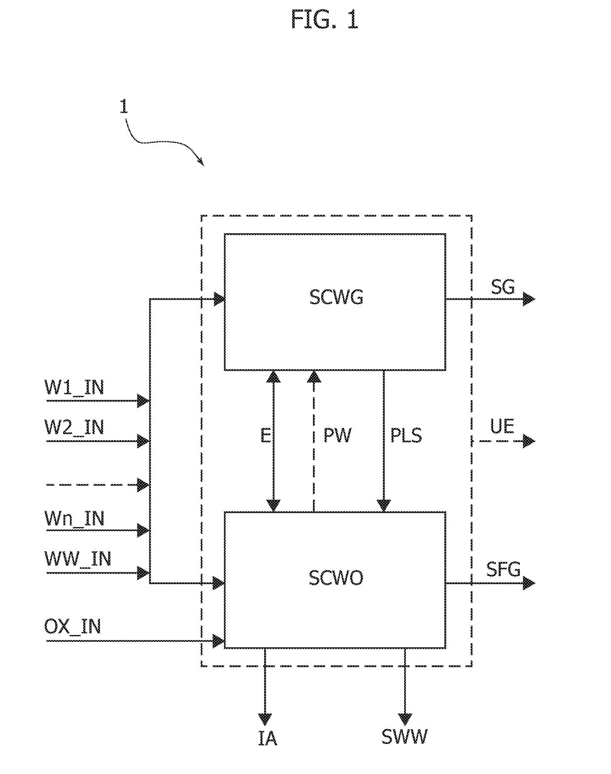
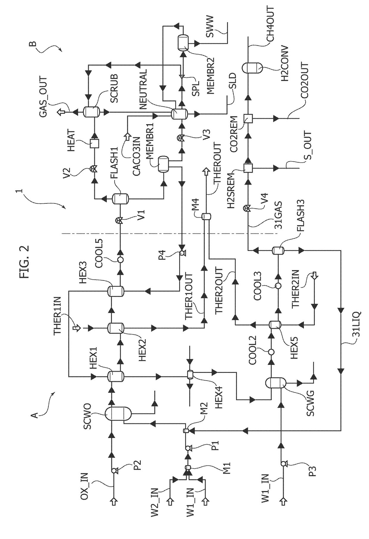
[0035]With reference to FIG. 1, a waste-disposal plant and a corresponding disposal method according to various embodiments of the invention may represented schematically as illustrated here. In this connection, the reference number 1 designates as a whole the diagram of FIG. 1, which can be deemed equivalent both for the waste-disposal plant and for the waste-disposal method according to the invention.

[0036]In particular, the plant 1 includes a supercritical-water gasification reactor, designated by the reference SCWG, a supercritical-water oxidation reactor, designated by the reference SCWO, and a feeding system, which is able to feed to the plant 1 at least one aqueous current and at least two organic currents of waste. It should be noted that, for the purposes of the present description, by the term “feeding system” is meant a set of devices capable of feeding the waste at input to the plant 1 but also within the plant 1 itself, where by the term “waste” is in turn meant any com...


PUM

PropertyMeasurementUnit
currentaaaaaaaaaa
flow rateaaaaaaaaaa
liquid phase flowaaaaaaaaaa

Abstract

A plant for the disposal of wastes includes a supercritical water oxidation reactor, a supercritical water gasification reactor, and a feeding system configured for feeding at least two organic currents of wastes to the supercritical water oxidation reactor and supercritical water gasification reactor and configured for feeding at least one aqueous flow within said plant. The feeding system is configured for feeding the at least one aqueous current with a series flow through the supercritical water oxidation reactor and supercritical water gasification reactor. The feeding system is configured for feeding the at least two organic currents of wastes with a parallel flow through the supercritical water oxidation reactor and supercritical water gasification reactor and so as to selectively feed each of the organic currents of wastes to the supercritical water oxidation reactor or to the supercritical water gasification reactor.

Description

FIELD OF THE INVENTION[0001]The present invention relates to a waste-disposal plant and to a corresponding disposal method, characterized by high energy efficiency. The present invention has moreover been developed with particular reference to plants in which, in addition to disposal, recovery of the disposed waste is envisaged, with simultaneous production of biofuels and conversion of energy for external use.PRIOR ART AND GENERAL TECHNICAL PROBLEM[0002]Disposal of waste is so far basically provided in a way specific for the type of waste treated. In particular, for given types of waste that is dangerous for the environment and human health it is necessary to envisage separate treatment plants provided with systems for after-treatment of the reaction products that will enable release into the atmosphere of just harmless species.[0003]A technology consolidated in the sector is that of incinerators, which, however, are affected by limits of performance due to the substantial impossib...

Claims


Application Information

Patent Timeline
Patent Type & Authority Applications(United States)
IPC IPC(8): B01J19/00B01J3/00B01D19/00C02F11/08C10J3/78C10J3/86F28D1/02B09B3/00A61L11/00
CPCB01J19/0053B01J3/008B01D19/0073C02F11/086C10J3/78C10J3/86F28D1/0226B09B3/00A61L11/00C02F2101/101C02F2303/10C10J2300/0979C02F2101/20C02F2101/301C02F2101/306C02F2101/32C02F2103/002C02F2103/008C02F2103/06C02F2103/10C02F2103/24C02F2103/28Y02W10/30Y02P20/54Y02P20/129Y02E20/12C02F11/08C10J3/00H05K999/99
Inventor BRUCATO, ALBERTOCAPUTO, GIUSEPPEGRISAFI, FRANCOSCARGIALI, FRANCESCATUMMINELLI, GIANLUCATUZZOLINO, GAETANOD'AGOSTINO, ROBERTORIZZO, ROBERTO
Owner ARCHIMEDE
Why Eureka
Try Eureka