Method of making three-flow-passage valve with a pressure indicator

a pressure indicator and flow-passage valve technology, applied in hydrodynamic testing, instruments, machines/engines, etc., can solve the problems of prolonging the life of the valve, and achieve the effect of reducing friction, and reducing the risk of leakag

Inactive Publication Date: 2018-05-03
DI MONTE MICHAEL ANTHONY
View PDF2 Cites 13 Cited by
  • Summary
  • Abstract
  • Description
  • Claims
  • Application Information

AI Technical Summary

Benefits of technology

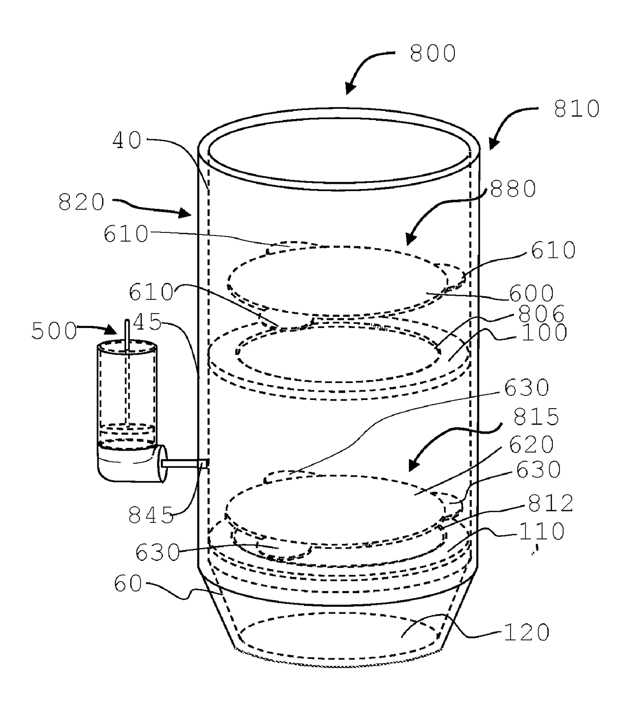
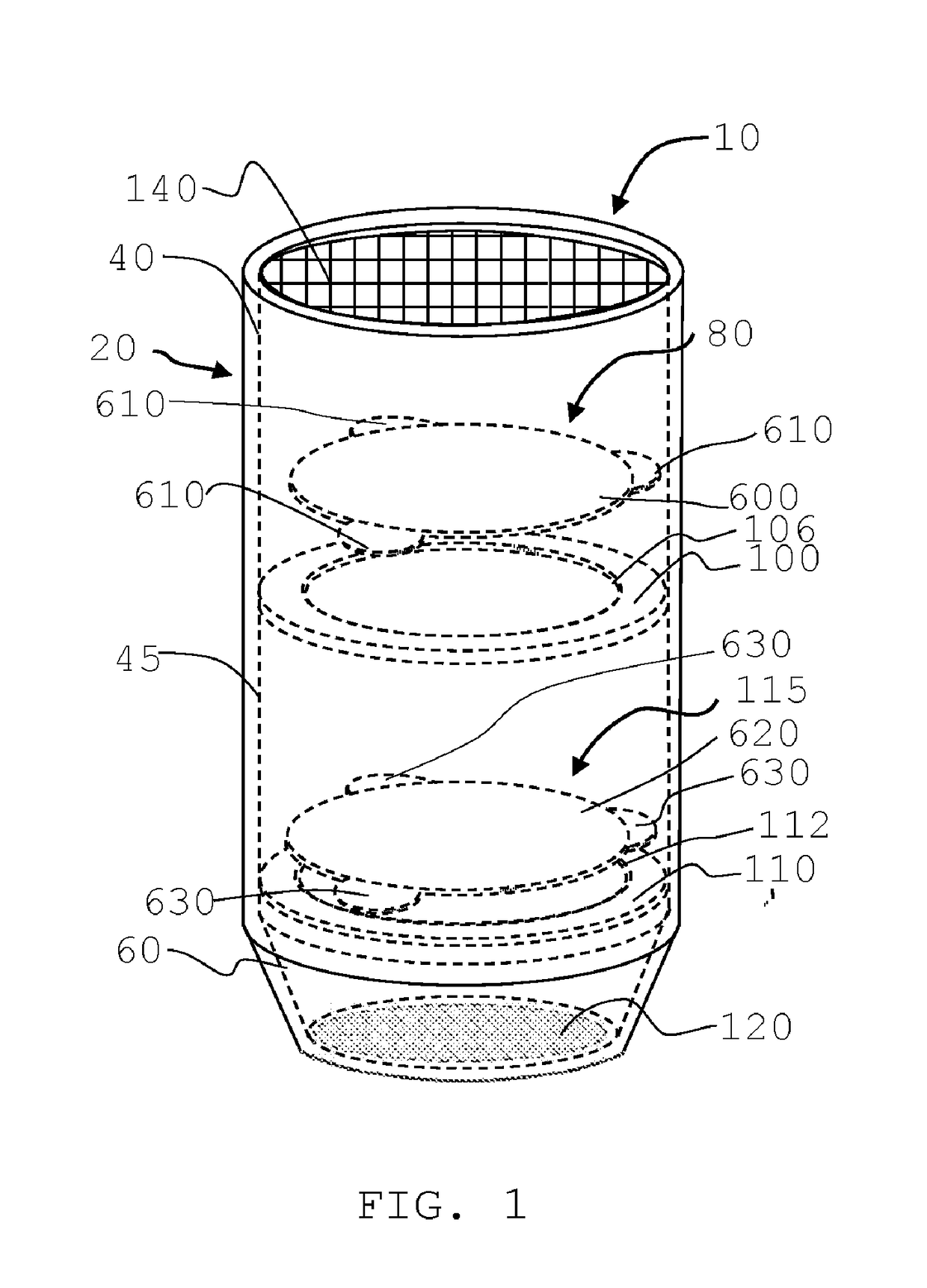
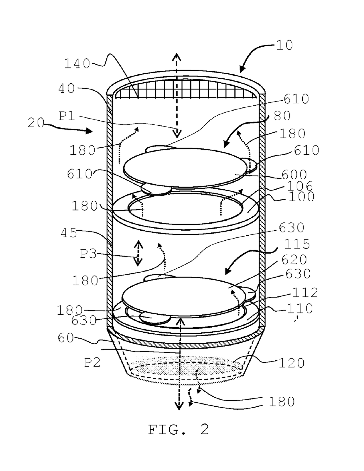
[0008]This Brief Summary is included so as to introduce, in an abbreviated form, various topics to be elaborated upon below in the Detailed Description. This Brief Summary is not intended to identify key or essential aspects of the claimed invention. This brief Summary is similarly not intended for use as an aid in determining the scope of the claims. The subject matters of this application overcomes the aforementioned problems and is directed to a method of making a three-flow-passage valve with a pressure indicator, comprising the steps of (a) constructing a first half housing defining an upper flow passage, a middle flow passage, and a lower flow passage, wherein the upper flow passage is constructed above the middle flow passage, wherein the middle flow passage is constructed above the lower flow passage; (b) constructing a second half housing defining an upper flow passage, a middle flow passage, and a lower flow passage, wherein the upper flow passage is constructed above the middle flow passage, wherein the middle flow passage is constructed above the lower flow passage; (c) forming an access port through the housing in the middle flow passage; (d) forming a first valve seat between the upper flow passage and the lower flow passage, wherein at least one valve opening is further formed on the first valve seat; (e) assembling at least one movable valve opening stopper in the upper flow passage and above the first valve; (f) adjusting the at least one movable valve opening stopper to allow the at least one movable valve opening stopper to plug or unplug the at least one valve opening on the first valve seat; (g) forming a second valve seat between the upper flow passage and the lower flow passage, wherein at least one valve opening is further formed on the second valve seat; (h) assembling at least one movable valve opening stopper in the upper flow pass

Problems solved by technology

The rotation of the rotary valve will allow the contact points of the valve and the valve seat to constantly rotate and change, which will prolong the life of the valve.
The guide rails will allow the rotary va

Method used


Image

  • Method of making three-flow-passage valve with a pressure indicator
  • Method of making three-flow-passage valve with a pressure indicator
  • Method of making three-flow-passage valve with a pressure indicator

Examples


Embodiment Construction

[0051]Before the present invention is described in greater detail, it is to be understood that this invention is not limited to particular embodiments described, and as such may, of course, vary. It is also to be understood that the terminology used herein is for the purpose of describing particular embodiments only, and is not intended to be limiting, since the scope of the present invention will be limited only by the appended claims.

[0052]Where a range of values is provided, it is understood that each intervening value, to the tenth of the unit of the lower limit unless the context clearly dictates otherwise, between the upper and lower limits of that range is also specifically disclosed. Each smaller range between any stated value or intervening value in a stated range and any other stated or intervening value in that stated range is encompassed within the invention. The upper and lower limits of these smaller ranges may independently be included or excluded in the range, and ea...


PUM


Abstract

A method of making a three-flow-passage valve with a pressure indicator, comprising the steps of constructing a first half housing defining an upper flow passage, a middle flow passage, and a lower flow passage; constructing a second half housing defining the same flow passages; forming an access port through the housing in the middle flow passage; forming a first valve seat with one valve opening; assembling one movable valve opening stopper in the upper flow passage; adjusting the one movable valve opening stopper; forming a second valve seat with one valve opening; assembling one movable valve opening stopper in the upper flow passage; adjusting the one movable valve opening stopper to allow the one movable valve opening stopper in the middle flow passage; combining and sealing the first half housing with the second half housing; and mounting a pressure indicator to the access port.

Description

BACKGROUND[0001]A variety of air admittance valves have been made over the years for allowing air to enter a piping system or an enclosed environment under a negative or vacuum pressure, which is created when water is flowing down the drain for instance thus to preventing siphoning of traps or when a sump pump keeps pumping water and air out of an enclosed sump pit. Attaching an air admittance valve allows ambient air to enter the enclosed environment to eliminate negative pressure or vacuum in the enclosed system. Many of these products are specifically or only designed for systems such as piping systems and sewer systems where a local vent or air intake is not possible or due to the difficulty of running pipes through an already built home. Typically, these air admittance valves only provide specific operating conditions such as the vacuum pressure in the amount of air required. The air admittance valves available in the market today do not provide for an instantaneous and higher ...

Claims


Application Information

Patent Timeline
IPC IPC(8): G01M10/00G01R31/34G01M13/02F03B11/00
CPCG01M10/00G01R31/34G01M13/02F03B11/008F05B2260/83E03C1/1225F16K24/06F16K15/042F16K15/048F16K17/12Y02E10/20
Inventor DI MONTE, MICHAEL ANTHONY
Owner DI MONTE MICHAEL ANTHONY
Why Eureka
Try Eureka