Fully Integrated Hybrid Electric Jet Engine

a hybrid electric jet engine and fully integrated technology, applied in the direction of liquid fuel engines, machines/engines, efficient propulsion technologies, etc., can solve the problems of performance detriment, not intended for high-power applications, etc., to increase the air gap radius/air gap speed, reduce windage losses, and increase power density

Active Publication Date: 2018-05-10
CODRIN GRUIE CG CANTEMIR
View PDF0 Cites 26 Cited by
  • Summary
  • Abstract
  • Description
  • Claims
  • Application Information

AI Technical Summary

Benefits of technology

[0012]The location of the electric machine takes also advantage of the mid-box structure which is the most rigid part of a jet engine.
[0013]In order to accommodate the core geometry, the electric machine has a configuration generically known as “ring type”. Such configuration does not use most of the internal geometry for electromagnetic purposes. Thus it is possible to design such machines with a very sizable hollow shaft and to connect the LP compressor with the HP compressor thru a passage inside the machine shaft. Particularly, the “ring type” configuration is also advantageous due an increased air gap radius / air gap speed and thus an increase power density. Practically, the air gap speed may be higher than the highest tip speed in the LP compressor, around 250 m / s while the rotor OD will still fits inside the inner geometry of the by-pass duct. In order to decrease the windage losses the air gap is sealed from the exterior and the air inside the machine is removed continuously with a vacuum pump.
[0014]In order to further increase the power density, the electric machine is designed with VCSC (Variable Cross-Section Coils) technology ring coils. The base idea of a variable cross-section coil resides in the fact that the slot itself represents a geometric bottleneck, however outside of the slot is more geometry available and a higher cross-section conductor may be implemented. Due to the fact that the length of the conductor outside of the slot is in most cases sensibly longer than inside the slot, it is possible to obtain significant gains in decreasing the coils resistance. Practically, the VCSC technology permits the usage of aluminum (vs. copper) while decreasing the total weight 2 to 3 times for the same electric resistance.
[0015]Another particularity of such implementation is the fact that the power electronic modules are located in the very close vicinity of the coils. It is desirable that each coil will be controlled independently by an individual (monophasic) inverter and thus the power level per module will not exceed 300 kVA—a very reasonable load for many semiconductor technologies.
[0016]Furthermore, the power electronic and the coils are sharing the same cooling circuit. The maximum total heat which need to be dissipated may be over 1 MW at RTO. Therefore the heat is dumped in the by-pass duct in order to provide extra thrust. For the reader intuition, dumping 1 MW in the by-pass may create an additional 700 N of thrust at cruise condition, therefore some 200 kW at the airframe. This may be equivalent with a net increase with 1% absolute (e.g. from 0.94 to 0.95) of the system efficiency. In order to dissipate the heat, it is preferable that the fan booster to act also as a heat exchanger. Additionally a surface heat exchanger may be located in the duct, both solutions having the advantage of dissipating heat without introducing pressure losses in the duct flow.

Problems solved by technology

Overall, such solutions were not intended for high power applications in which flight can be fully sustained only by electric energy.
Therefore, if existing solutions will be sized as a “plug-in hybrids”, then performances will be detracted due to extra gearing and / or distortion of the optimal flow geometry and / or lack of available geometry for the integration of a good-sized electric machine.

Method used


Image

  • Fully Integrated Hybrid Electric Jet Engine
  • Fully Integrated Hybrid Electric Jet Engine
  • Fully Integrated Hybrid Electric Jet Engine

Examples


Embodiment Construction

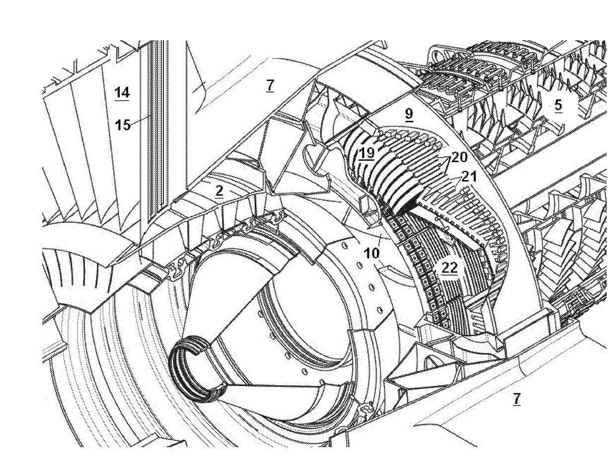
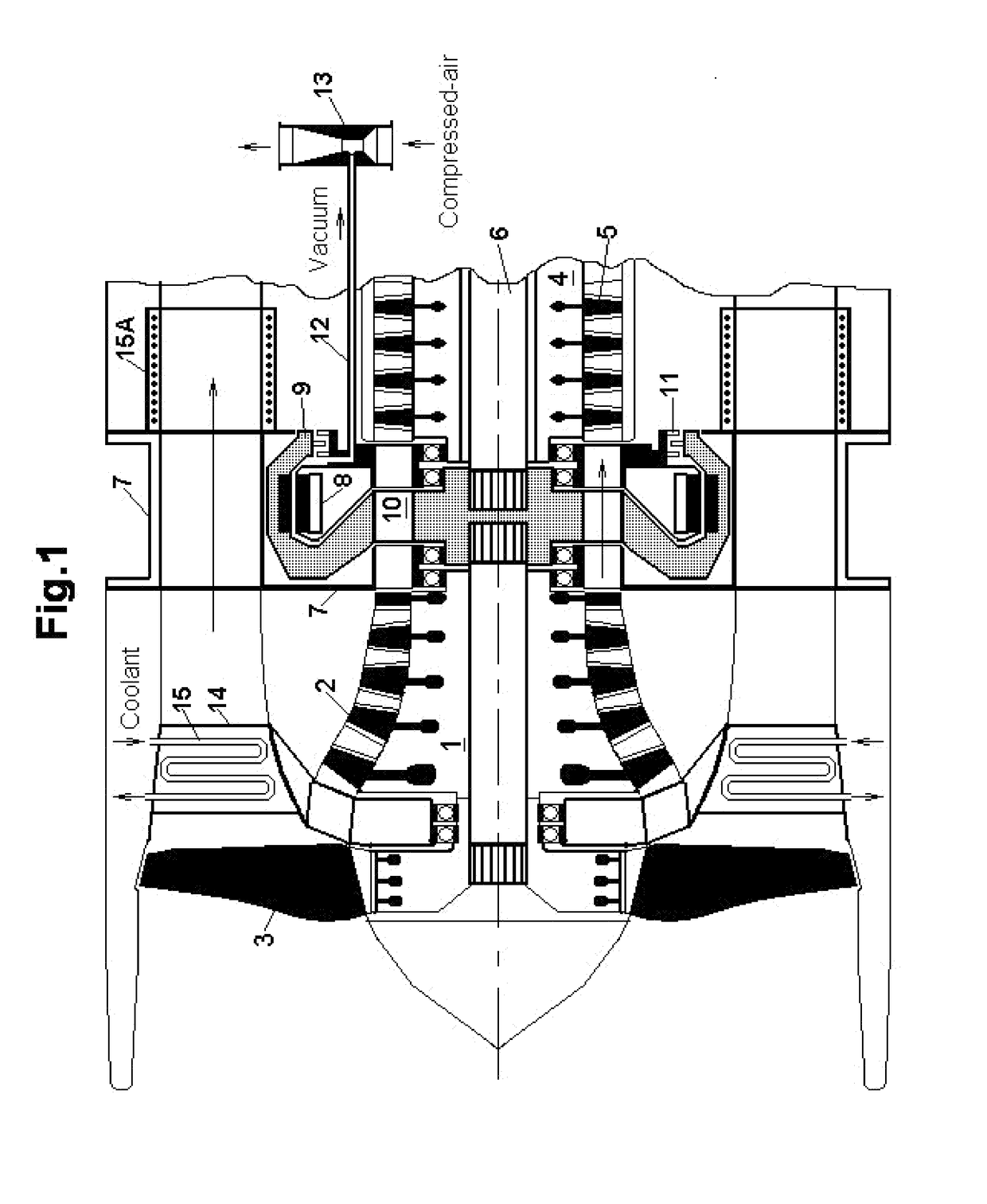
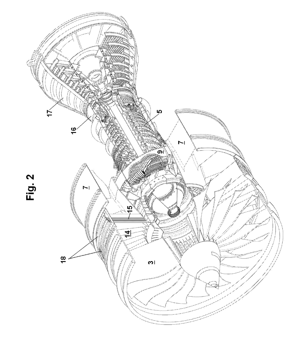
[0022]Referring to the drawings, FIG. 1 represents a generic representation of a hybrid electric turbofan jet engine from which the combustion section and the turbines were removed. The configuration of the turbofan engine is a classic two shafts spinning freely, with the LP shaft 1 supporting the LP compressor 2 and the main fan 3. The HP shaft 4 is supporting the HP compressor 5 and is driven in a conventional manner by a LP turbine (not figured). The LP shaft 1 is driven by a LP turbine (not figured) via a torque shaft 6. In general the speeds between the shafts are significantly different, e.g. by a factor of 2.5 to 3. The turbofan engine assembly is mounted around a mid-box 7 which acts also as the main structural part. A ring type electric motor 8 is also mounted inside the mid-box 7. The rotor 9 of the motor 8 is resiliently coupled to the LP shaft 1 and to the torque shaft 6. The rotor 9 is designed with profiled (curved) spokes 10 in order allow an unrestricted airflow pass...


PUM


Abstract

Disclosed is a high-power electric motor and its fabrication technology. The motor and its distributed power electronics are all being fully integrated in a conventional turbofan engine. The rotor drives directly (with no gears) the LP shaft of the jet engine while requiring minimal modification to a basic jet engine and without distortion to the nacelle geometry. In principle such a configuration should be suitable for a power level of 10 to 50 MW, which makes it fully capable of providing a standard flight envelope by only using electric energy.

Description

CROSS REFERENCE TO RELATED APPLICATIONS[0001]This application claims priority to U.S. provisional applications No. 62 / 240122 filed on 12 Oct. 2015 and to U.S. provisional applications No. 62 / 404224 filed on 5 Oct. 2016.STATEMENT OF GOVERNMENT INTEREST[0002]The Government of the United States of America may have rights in the present invention as a result of Grant No. NNX14AL87A awarded by NASA, with the exception of certain technical solutions and technologies implemented in present invention which have been developed independently and have been presented to NASA prior the award.BACKGROUND OF THE INVENTION1) Field of Invention[0003]The present invention is directed to a hybrid electric gas turbine engine, in particular a high by-pass turbofan engine for aircraft propulsion.2) Prior Art[0004]Gas turbine engines assisted by electric machines are known in the art. However, existing solutions are mostly conceived as “mild hybrids”. Benefits of mild hybridization are typically beneficial...

Claims


Application Information

Patent Timeline
Patent Type & Authority Applications(United States)
IPC IPC(8): B64D27/16H02K9/06H02K3/28F04F5/20F04D29/053H02K11/33F04D19/02F04D27/00B64D27/24B64D27/02
CPCB64D27/16F04D19/02F04D27/009F04F5/20B64D2027/026B64D27/24H02K11/33H02K3/28H02K9/06F04D29/053F01D15/10F02C7/32F02K3/06F02K5/00F05D2220/76H02K1/146H02K3/12H02K3/18H02K3/50H02K3/524H02K7/14H02K21/225Y02T50/60F02C6/00F02K3/00
Inventor CANTEMIR, CODRIN-GRUIE
Owner CODRIN GRUIE CG CANTEMIR
Why Eureka
Try Eureka