
Tactile feedback device

Active Publication Date: 2018-05-10
RES & BUSINESS FOUNDATION SUNGKYUNKWAN UNIV
View PDF17 Cites 3 Cited by
  • Summary
  • Abstract
  • Description
  • Claims
  • Application Information

AI Technical Summary

Benefits of technology

The patent text describes a new type of tactile feedback device that overcomes limitations of previous devices. The device uses electrostatic force to create a tactile feedback and includes a low carrier concentration and minimizing electric field shielding. Additionally, the device is made with a pressure-transfer protrusion that is lightweight and compatible with human skin. The technical effects of this invention include improved structural and performance capabilities, making it more efficient and comfortable to use.

Problems solved by technology

In the case of electrical stimulation, it is difficult to deliver accurate tactile information due to a large difference from actual tactile information.
In the case of mechanical stimulation, practical application is difficult due to the complexity of components of the mechanical tactile device, large volume, high driving power, and the like, thereof.
However, existing actuators have a number of technical limitations.
Disadvantages of such actuator devices may include followings: eccentric motor—long response time, linear resonance—weak durability, piezoelectricity—high power consumption requirement, electroactive polymer—high electrical potential difference requirement, and electrostatic force—local tactile feedback being disabled.
Due to the limitations of these devices, the current tactile feedback technology is still lacking in terms of completeness.

Method used


Image

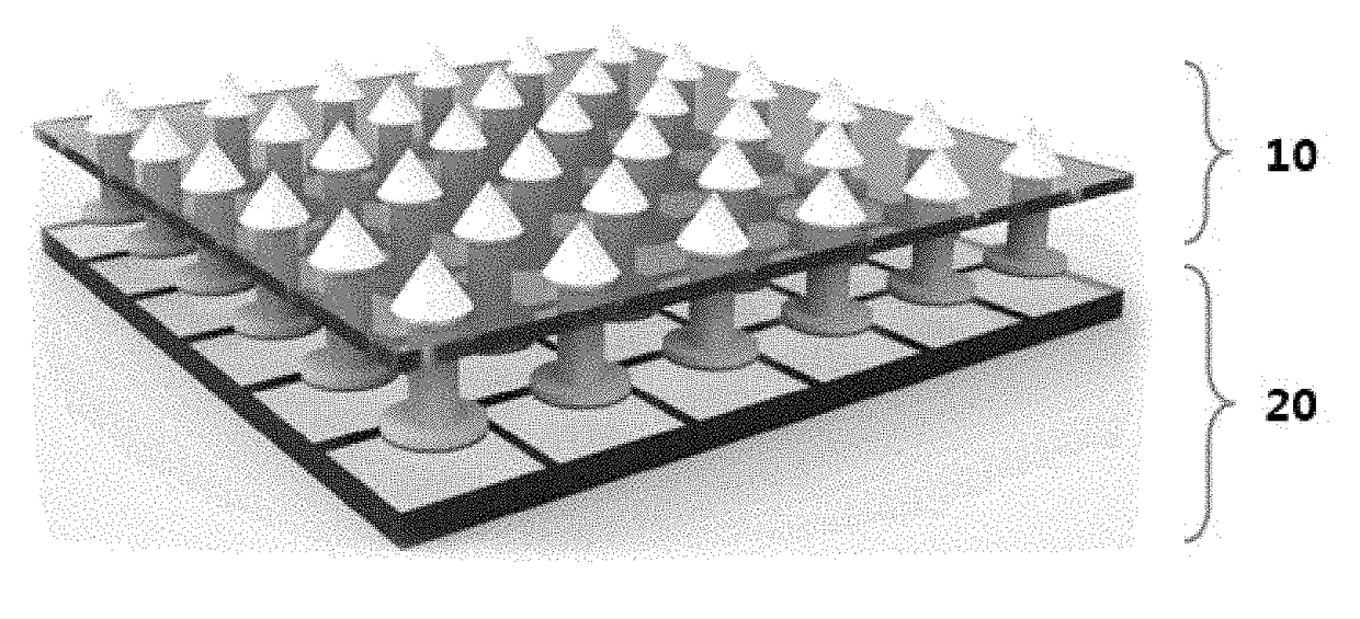
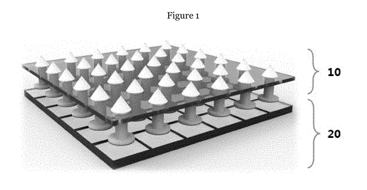
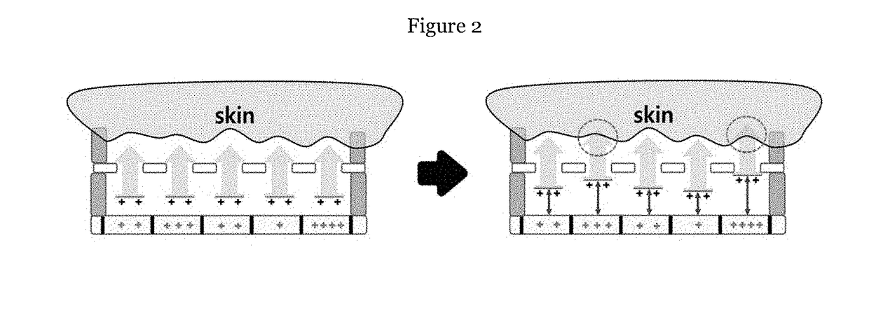
  • Tactile feedback device
  • Tactile feedback device
  • Tactile feedback device

Examples


Embodiment Construction

[0038]Examples of various embodiments are illustrated and described further below. It will be understood that the description herein is not intended to limit the claims to the specific embodiments described. On the contrary, it is intended to cover alternatives, modifications, and equivalents as may be included within the spirit and scope of the present disclosure as defined by the appended claims.

[0039]It will be understood that, although the terms “first”, “second”, “third”, and so on may be used herein to describe various elements, components, regions, layers and / or sections, these elements, components, regions, layers and / or sections should not be limited by these terms. These terms are used to distinguish one element, component, region, layer or section from another element, component, region, layer or section. Thus, a first element, component, region, layer or section described below could be termed a second element, component, region, layer or section, without departing from ...


PUM


Abstract

There is provided a tactile feedback device comprising: an array of surface charge generation units; and an array of pressure-generation units, wherein the array of the pressure-generation units is spaced apart from the array of the surface charge generation units, wherein the array of the pressure-generation units is movable relative to the array of the surface charge generation units, wherein an attractive or repulsive force is generated between a corresponding surface charge generation unit of the array of surface charge generation units and a corresponding pressure-generation unit of the array of the pressure-generation units, based on a polarity of surface charges induced in the corresponding surface charge generation unit.

Description

CROSS-REFERENCE TO RELATED APPLICATION[0001]This application claims the benefit of Korean patent application No. 10-2016-0147978 filed on Nov. 8, 2016, the entire content of which is incorporated herein by reference for all purposes as if fully set forth herein.BACKGROUNDField of the Present Disclosure[0002]The present disclosure relates to a tactile feedback device for use in a virtual reality device and an augmented reality device for realizing imitation reality.Discussion of Related Art[0003]When precise tactile feedback technology is added to VR (Virtual Reality) or AR (Augmented Reality) technology, which allows more intuitive feedback of information about real objects or virtual objects, it is possible to implement imitation reality which is more realistic than the virtual reality.[0004]The current information acquisition approach is evolving from an approach of acquiring audiovisual information (text, picture, video, etc.) via PC, smart phone, etc. to VR and AR approach of ac...

Claims


Application Information

Patent Timeline
IPC IPC(8): G06F3/01
CPCG06F3/016G06F3/011G09B21/004H02N1/002H10N30/50H10N30/30H10N30/85
Inventor KIM, SANG WOOSEUNG, WAN CHULYOON, HONG JOONKWAK, SUNG SOOKIM, DONG HOONKIM, TAE YUNKANG, MIN KILEE, KANG HYUCKKIM, SUNG KYUNLEE, JEONG HWANKIM, SEONG SU
Owner RES & BUSINESS FOUNDATION SUNGKYUNKWAN UNIV
Learn More