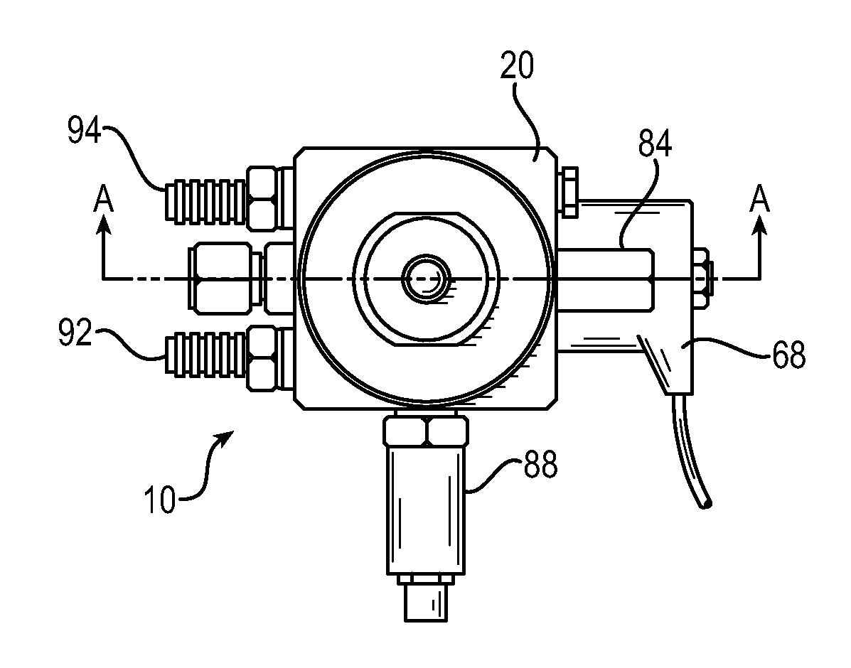
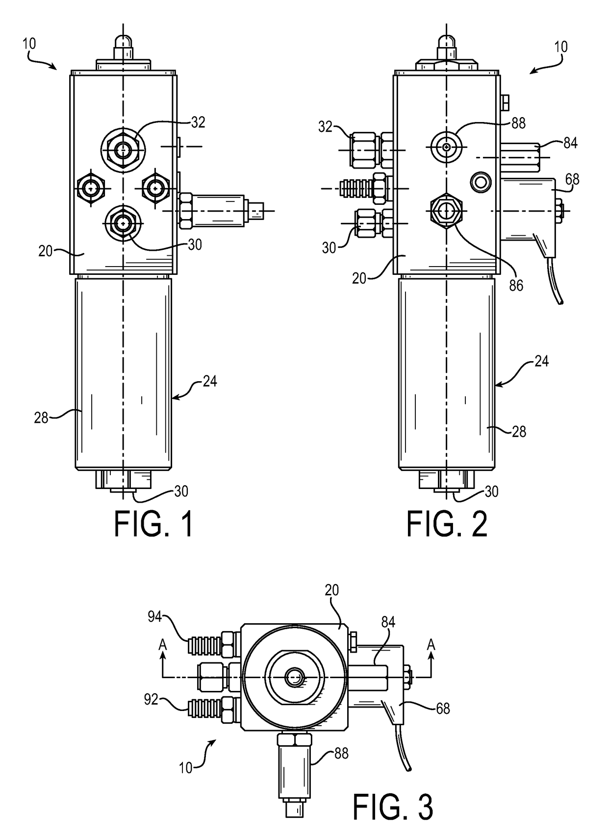
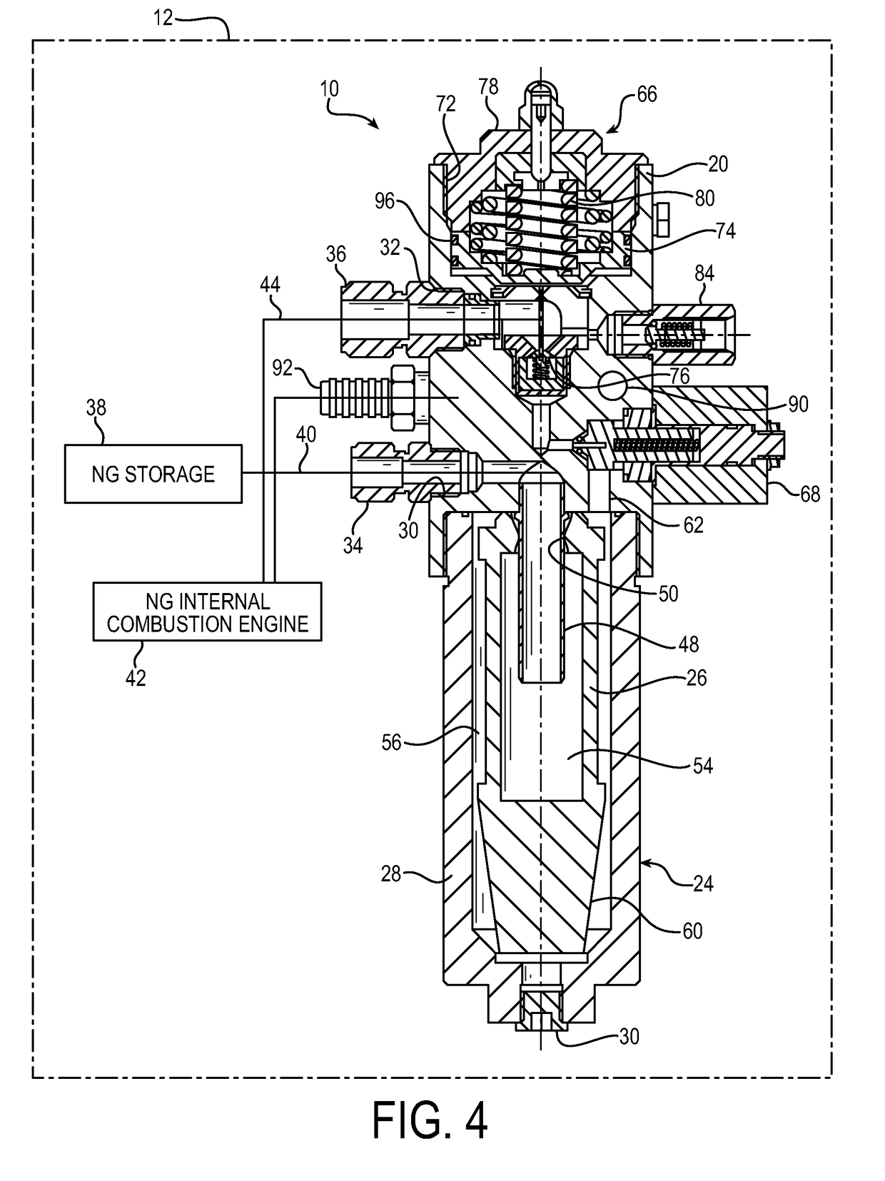
[0035]Referring now in detail to the drawings and initially to FIGS. 1-4, an exemplary fuel management module according to the present invention is indicated generally by reference numeral 10. The module is intended for use onboard a natural gas vehicle (NGV) (represented by the broken outline 12 in FIG. 4) for fuel pressure regulation and conditioning of natural gas (NG) temperature for improved engine performance and reduced emissions in the vehicle. Although the module 10 and associated system and method are herein described in relation to conditioning NG in a NGV, it will be appreciated by those skilled in the art that the module, system and method may have other applications, including use with fluids other than NG.
[0036]The module 10 is comprised of a manifold 20 (or more particularly a unitary manifold block) which houses components and subsystems used for the conditioning of NG fuel. The manifold 12 preferably is made of aluminum or another suitable material preferably having a thermal conductivity at 25 degrees C. of at least 15 W/(m K), such as for example stainless steel.
[0037]Integrated into the module 20 is a filter assembly 24 including a filter element 26 and a filter housing 28 (also referred to as a bowl) that is mounted to the manifold 12. The filter housing preferably is removably attached to the manifold so that the filter element can be replaced as needed. In the illustrated embodiment, the filter housing is threaded at its upper end for threading into a threaded bore at the underside of the manifold.
[0038]For reasons discussed in greater detail below, the filter housing 28 preferably is made of aluminum or other suitable material preferably having a thermal conductivity at 25 degrees C. of at least 15 W/(m K), such as for example stainless steel. In addition, the filter housing is in thermally conductive relationship with the manifold such that heat can flow from the manifold to the filter housing for thermal conditioning of the high pressure natural gas as well as providing high pressure filtration.
[0039]The filter element 26 may be a coalescing filter element. In the illustrated embodiment, flow of the NG is from the inside to the outside of the filter element. Any water contained in the NG will coalesce and flow to the bottom of the filter housing 28. The filter housing may be equipped with a bottom plug 30 that may be removed to drain captured water from the filter housing.
[0040]With particular reference to FIG. 4, the manifold 20 has an inlet port 30 and an outlet port 32 for the natural gas. The inlet and outlet ports may have fittings 34 and 36 threaded therein to provide for convenient connection to gas flow lines. The inlet port normally would be connected to a supply of/storage 38 for of liquefied or compressed natural gas, as by line 40, while the outlet port would be connected to a natural gas internal combustion engine 42, as by line 44.
[0041]The inlet port 30 communicates with a center tube 48 that extends into the interior of the filter element 26 such that the natural gas entering the filter element will be introduced about midway along the length of the tubular filter media portion of the filter element. The center tube may be threaded into a bottom bore in the manifold 20 or otherwise secured to the manifold.
[0042]The filter element 26 has at its upper end an annular seal 50 that seals to the outer diameter of the center tube 48. The seal isolates the interior 54 of the filter element from an annular region 56 formed between the exterior of the filter element and the radially outwardly spaced wall of the filter housing 28 that surrounds the filter element.
[0043]The lower end of the filter element 26 has a bottom closure member 60 of frusto-conical shape that abuts a bottom wall of the filter housing 28. The upper end of the frusto-conical closure member defines a narrow annular passage for water to flow from an upper region of the filter housing to the lower region of the filter housing while minimizing splashing of water in the lower region into the annular region 56 that might otherwise occur when the natural gas vehicle goes over bumps.
[0044]The annular region 56 communicates with a passage 62 in the manifold 20 that opens to the bottom of the manifold. NG will flow from the filter assembly 24 to a pressure regulator assembly 66 that may be of conventional type. The rate of flow to the pressure regulator may be controlled by a flow control valve 68 and in particular a solenoid operated valve that may be connected to a suitable controller in the vehicle. Flow exiting the pressure regulator passes to the outlet port 32 that will be connected to the NG internal combustion engine 42.
[0045]In some applications, the flow control valve 68 may function simply as a shut-off valve for shutting off flow of NG to the internal combustion engine. The flow control valve preferably is a cartridge valve threaded into manifold.
[0046]The pressure regulator assembly 66, on the other hand, may be assembled directly into a bore 72 opening to the top of the manifold 20. In particular, the pressure regulator assembly may include a piston 74 that is guided for axial movement in the bore 72 of the manifold, which piston operates the metering valve 76 of the pressure regulator. The outer (upper) end of the bore may be closed by a cover 78, and the regulator springs 80 may be interposed between the cover and the piston as illustrated.
[0047]In addition, the module 10 may have integrated therein a pressure relief valve 84, which preferably is a cartridge relief valve threaded into a threaded bore in the manifold that communicates with the gas flow passage through the manifold. The pressure relief valve can protect the engine's fuel rail from over-pressurization.
[0048]In addition, various sensors may be integrated into the module 10, including pressure and temperature sensors for providing feedback to a controller that controls the NG delivery system. In particular, a cartridge pressure sensor 86 is threaded into the manifold for sensing the pressure in the line between the flow control valve and the pressure regulator. A further plug sensor 88 may be provided for sensing the reduced pressure downstream of the pressure regulator valve 76.
[0049]Further in accordance with the invention, the module 10 is provided with an integrated heating system for controlling the low temperature of the natural gas. The heating system includes a heat exchange fluid (also herein referred to as a heat exchange media) flow path 90 in the manifold that extends between an inlet port 92 and an outlet port 94. The heat exchange media flow path may be configured to provide the desired amount of surface area between the heat exchange media and the manifold for effective heating of the manifold.
[0050]It is noted that heat exchange media passage(s) forming the flow path 90 are isolated by internal metal walls of the manifold 20 from the natural gas flow passages media through the manifold thereby preventing any contamination of the heat exchange fluid with natural gas on the one hand and any contamination of the nature gas with the heat exchange fluid on the other hand. This is effected without the need for any seals.
[0051]The heat exchange pathway 90 in the manifold can accept engine coolant fluid from the water jacket of the engine 42. The jacket water, or engine coolant, provides an energy source at a relatively constant temperature (controlled by the engine thermostat). This energy source is used to establish and maintain a high temperature for the manifold. This energy is conducted through the metal manifold 20 and passed on to the balance of the module as well as the natural gas in contact with the manifold. As above mentioned, the radiator fluid flow path is isolated from the NG track by the internal walls of the module and is designed such that the fluid is isolated from the natural gas without the use of seals, fasteners, joints, connections or any such permeable boundary.
[0052]In addition, the heat conducted within the system is also made available to the particular areas of the internal seals, such as piston seals 96, within the module, enabling the seals to provide the function of sealing and protect against the negative effects of low temperature (degradation of sealing performance—reliability and durability).
[0053]Of particular significance is that the integration of filter assembly 24 into the module 10 enables the heat transfer to occur directly from the heated manifold block 20 to the filter housing 28.
[0054]In operation, compressed or liquefied natural gas is supplied to the inlet 30 of the module 10 from on-board fuel storage infrastructure 38. At this point in the fuel system the temperature of the natural gas approximates ambient temperature (for CNG systems), or the boiling point of NG (for LNG systems).
[0055]The filter assembly 24 being an integral part of the regulator system enables heat transfer to occur from the heated manifold 20 to the filter housing 28. Energy in the form of heat is transferred from the manifold to the filter housing through the threaded connection that joins these two components. This energy is then transferred to the NG at a high rate due to the large internal surface area of the filter bowl. The result is an impactful increase in temperature that establishes several design advantages: [0056] 1. Substantial heating of the NG by a controlled temperature heat source, prior to the point of pressure regulation, acts to raise the temperature of the NG near the temperature of said heat source (the engine jacket water), with minimized variance, despite environmental temperatures. [0057] 2. The potential for ice formation at the solenoid valve and seat assembly filter is reduced. [0058] 3. The module has an increased level of heat transfer to the gas without an additional heat source such as an electrical heater. [0059] 4. Freezing of any moisture present in the gas within the filter element is reduced if not eliminated. [0060] 5. Ice particle formation and travel downstream to the engine gas injectors is reduced if not eliminated.
[0061]Referring now to FIG. 5, the effect of the on-board fuel management module on fuel temperature homogenization is illustrated. At the left in the upper temperature graph, the upper band 100 represents the anticipated temperature range of incoming compressed gas whereas the lower band 102 represents the anticipated temperature range of incoming liquefied gas. As shown, the bands substantially narrow as the NG flows through the heated filter assembly and then the heated manifold, such that the temperature of the lower pressure NG leaving the module is in a substantially narrower range at the right of the graph.
[0062]Likewise, at the left in the lower density graph, the lower band 106 represents the anticipated density range of incoming compressed gas whereas the upper band 108 represents the anticipated density range of incoming liquefied gas. As shown, the bands converge as the NG flows through the heated filter assembly such that the density of the lower pressure NG leaving the module at the right in the graph is essentially the same regardless of whether the module receives higher temperature compressed gas or lower temperature liquefied gas.
[0063]Although the invention has been shown and described with respect to a certain preferred embodiment, it is obvious that equivalent alterations and modifications will occur to others skilled in the art upon the reading and understanding of this specification and the annexed drawings. In particular regard to the various functions performed by the above described components, the terms (including a reference to a “means”) used to describe such components are intended to correspond, unless otherwise indicated, to any component which performs the specified function of the described component (i.e., that is functionally equivalent), even though not structurally equivalent to the disclosed structure which performs the function in the herein illustrated exemplary embodiments of the invention. In addition, while a particular feature of the invention can have been disclosed with respect to only one of the several embodiments, such feature can be combined with one or more other features of the other embodiments as may be desired and advantageous for any given or particular application.