Single-shaft lens device for unmanned aerial vehicles

a single-shaft lens and unmanned aerial technology, which is applied in the field of unmanned aerial vehicles, can solve the problems of unfavorable miniaturization, heavy weight, and large volume of the uav, and achieve the effects of reducing the volume and weight of the aircraft housing, saving a larger exercise space, and simple assembling and dismantling manner

Inactive Publication Date: 2018-05-17
HAOXIANG ELECTRIC ENERGY KUNSHAN
View PDF2 Cites 3 Cited by
  • Summary
  • Abstract
  • Description
  • Claims
  • Application Information

AI Technical Summary

Benefits of technology

[0034]To better collect images, a lens shooting portion generally extends a distance relatively to other portions of the lens apparatus, and the lens apparatus rotates around the single shaft, which is able to save a larger exercise space and reduce a volume and weight of the aircraft housing of the UAV. The lens module is buckled with the lens front cover for eliminating the installation of screws, which is simple in assembling and disassembling manners and is able to reduce a whole weight and decrease the signal interference. Moreover, through tightly pressing the lens module to the lens front cover via the first circuit board, so as to further fix the lens module for obtaining a more stable installation manner.
[0035]Through the drawtube tank, the lens module is rapidly positioned, and the lens shooting portion extends outside a distance relatively to other portions of the lens apparatus; the buckling between the hooks and the lugs is able to complete the buckling during the process of downwardly pressing the lens module in the drawtube tank, so that the buckling manner is more stable and convenient.

Problems solved by technology

Among them, due to the need for rotation in multiple directions, the multi-shaft lens devices require a larger working space, so that the volume of the UAV will be too large, which is not conducive to miniaturization.
At present, the lens of the single-shaft lens device needs more screws to be fixed, so that the weight is heavy, and a certain amount of interferences occur.
Therefore, the accuracy of visual positioning is not high.
Moreover, the manner that the optical flow lens is mounted to the PCB is not easy to assemble.

Method used


Image

  • Single-shaft lens device for unmanned aerial vehicles
  • Single-shaft lens device for unmanned aerial vehicles
  • Single-shaft lens device for unmanned aerial vehicles

Examples


first embodiment

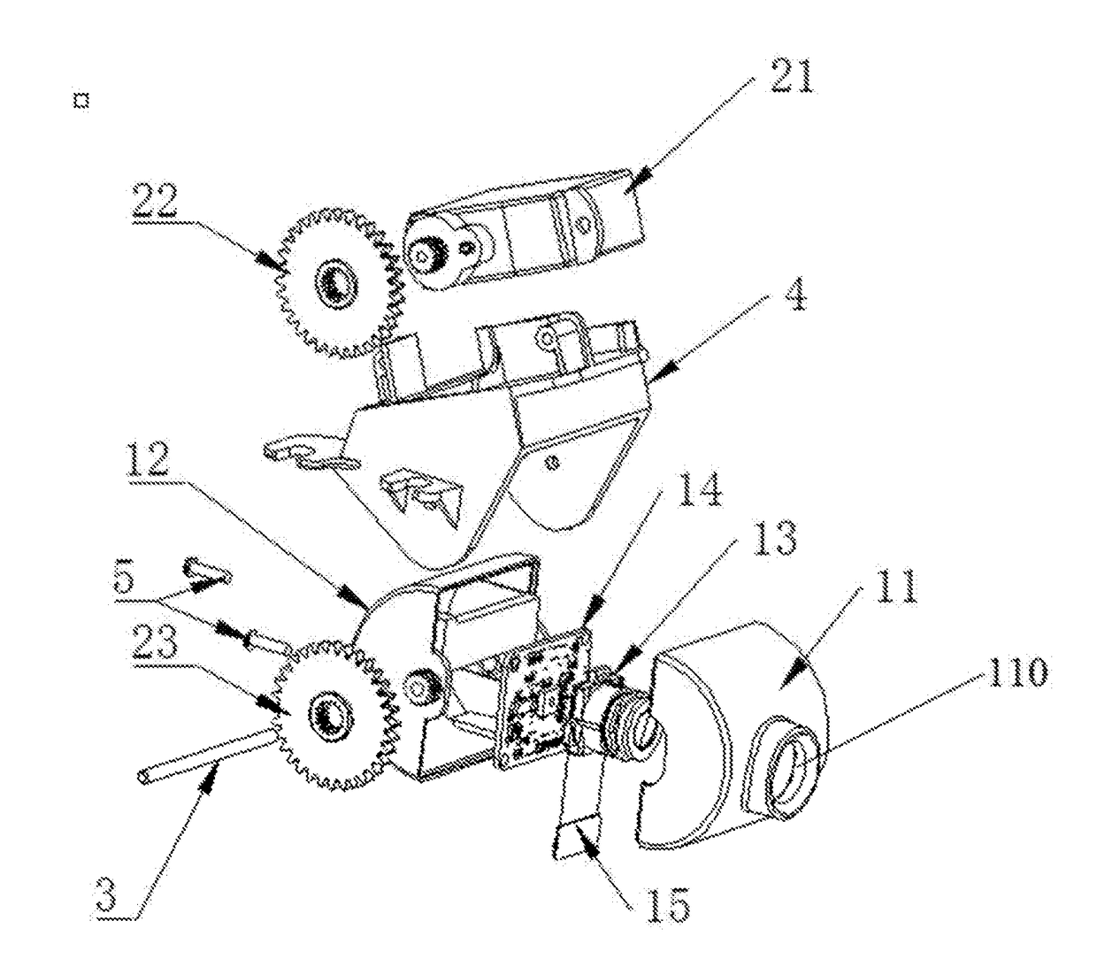
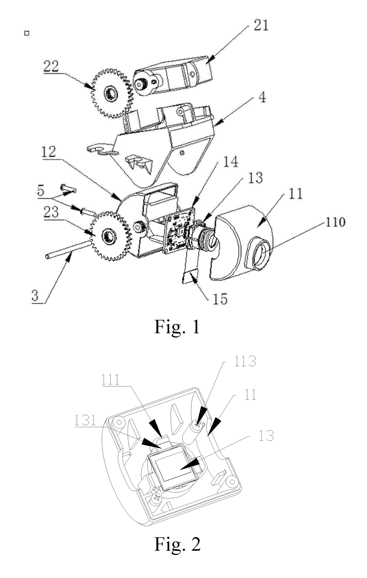
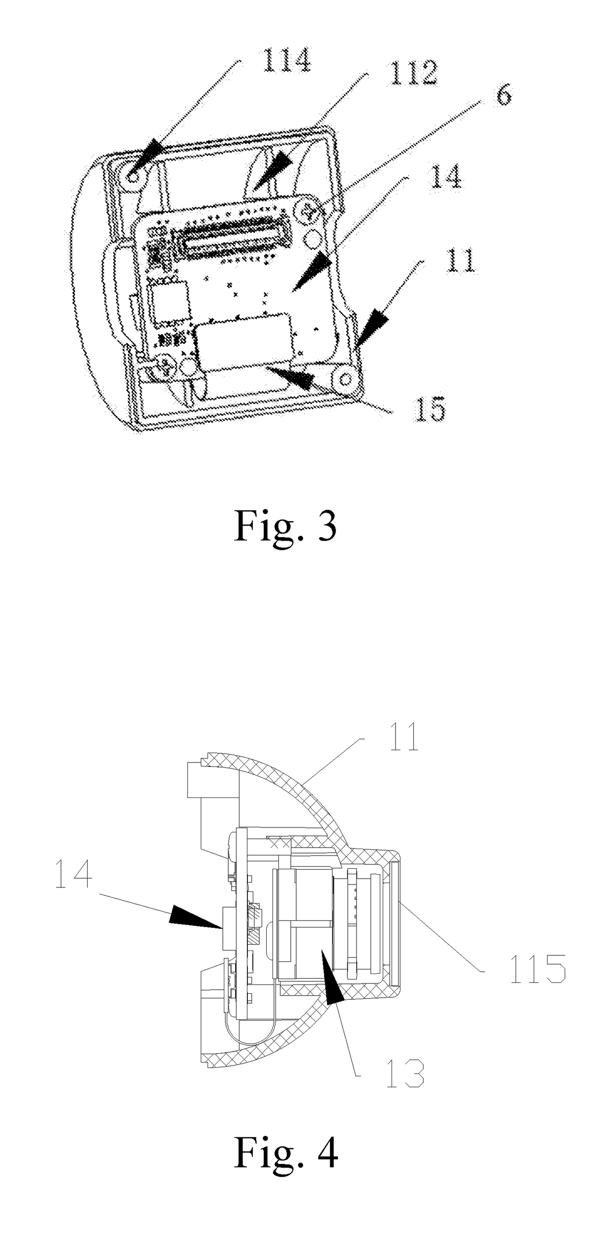
[0047]Referring to FIGS. 1 to 5, according to the present invention, a single-shaft lens device for a UAV (unmanned aerial vehicle) is illustrated, which comprises a drive apparatus and a lens apparatus, and is adapted for being installed into an aircraft housing of the UAV, wherein a control circuit in the aircraft housing is adapted for controlling the drive apparatus to drive, and the lens apparatus is driven through the drive apparatus to uniaxially rotate around a lens shaft 3.

[0048]The lens apparatus comprises a lens front cover 11, a lens rear cover 12, a lens module 13 and a first circuit board 14, which is not limited. The first circuit board 14 is able to be a circuit board installed with a sensor such as a gyroscope, which is not limited and also able to be a circuit board for preprocessing and transmitting data or a multi-functional integrated circuit board. The lens shaft 3 is sleeved to the lens front cover 11 or the lens rear cover 12. In FIG. 1, the lens shaft 3 is s...

second embodiment

[0061]Referring to FIGS. 6 to 8, an optical flow lens installation structure for a UAV according to the present invention is illustrated, which comprises an aircraft housing 40 and a second circuit board 30 located inside the aircraft housing 40, wherein the second circuit board 30 is able to be the main circuit board of the UAV which is not limited, and is at least a circuit board adapted for data exchanging with an optical flow lens unit 1.

[0062]The optical flow lens installation structure for the UAV comprises an optical flow support 2 and an optical flow lens unit 1. The optical flow support 2 is arched which means that the optical flow support 2 comprises an upwardly arched portion 200 and two arms 201 downwardly extended from two ends of the upwardly arched portion, respectively. As shown in FIG. 7, the arched portion 200 of the optical flow support 2 is an upwardly arched mesa, the two arms 201 of the optical flow support 2 are downwardly bent or folded (here, “upwardly” and ...


PUM


Abstract

A single-shaft lens device for a UAV (unmanned aerial vehicle), which includes a drive apparatus and a lens apparatus, wherein: the lens apparatus is driven through the drive apparatus to uniaxially rotate around a lens shaft; the lens apparatus includes a lens front cover, a lens rear cover, a lens module and a first circuit board; the lens shaft is sleeved to the lens front cover or the lens rear cover; the lens module is buckled with the lens front cover, the first circuit board tightly presses the lens module and is connected with the lens front cover, the lens rear cover is connected with the lens front cover after the lens rear cover is covered with the lens front cover.

Description

CROSS REFERENCE OF RELATED APPLICATION[0001]The present invention claims priority under 35 U.S.C. 119(a-d) to CN 201621449452.9, filed Dec. 27, 2016 and CN 201621449439.3, filed Dec. 27, 2016.BACKGROUND OF THE PRESENT INVENTIONField of Invention[0002]The present invention relates to a technical field of UAV (unmanned aerial vehicle), and more particularly to a single-shaft lens device for a UAV.Description of Related Arts[0003]Unmanned aerial vehicles are abbreviated as “UAVs”, which is operated with the radio remote control equipment and own program control device. UAVs are generally equipped with a lens device for image capture, the captured images are transmitted to the main control circuit of the UAV for processing. Existing lens devices include multi-shaft lens devices and single-shaft lens devices. Among them, due to the need for rotation in multiple directions, the multi-shaft lens devices require a larger working space, so that the volume of the UAV will be too large, which ...

Claims


Application Information

Patent Timeline
Patent Type & Authority Applications(United States)
IPC IPC(8): G02B7/02H04N5/225B64D47/08
CPCG02B7/023G02B7/021H04N5/2254B64D47/08B64C39/024B64C2201/123B64C2201/146G03B15/006G03B17/561H04N23/57H04N23/55B64U2101/30B64U2201/20
Inventor TIAN, YUJIANG, WENYAN
Owner HAOXIANG ELECTRIC ENERGY KUNSHAN
Why Eureka
Try Eureka