Organic electroluminescent element

a technology of electroluminescent elements and organic el, which is applied in the direction of organic chemistry, luminescent compositions, semiconductor devices, etc., can solve the problems of increasing the lifetime of phosphorescent emission-type organic el devices, and achieves the effects of low driving voltage, long lifetime and high luminous efficiency

Inactive Publication Date: 2018-05-17
NIPPON STEEL CHEMICAL CO LTD
View PDF0 Cites 5 Cited by
  • Summary
  • Abstract
  • Description
  • Claims
  • Application Information

AI Technical Summary

Benefits of technology

[0033]The organic EL device of the present invention can be an organic EL device having a low driving voltage, high luminous efficiency, and a long lifetime because the device contains a plurality of specific host materials in a light-emitting layer thereof.

Problems solved by technology

However, the lengthening of the lifetime of the phosphorescent emission-type organic EL device has been a technical problem.
However, a further improvement in efficiency has been required because the efficiency of the device is lower than that of a phosphorescent light-emitting organic EL device.

Method used


Image

  • Organic electroluminescent element
  • Organic electroluminescent element
  • Organic electroluminescent element

Examples


example 1

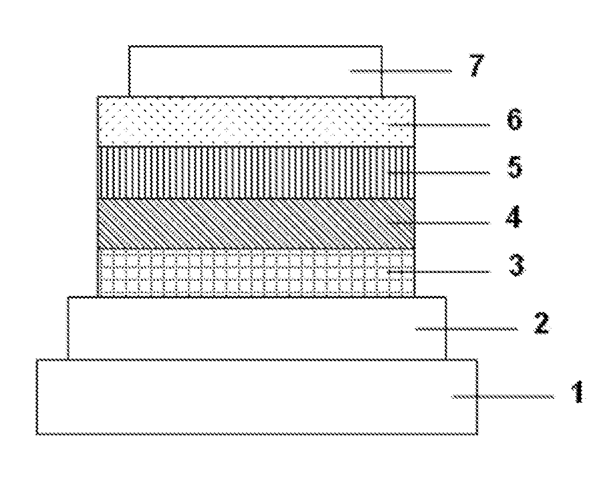
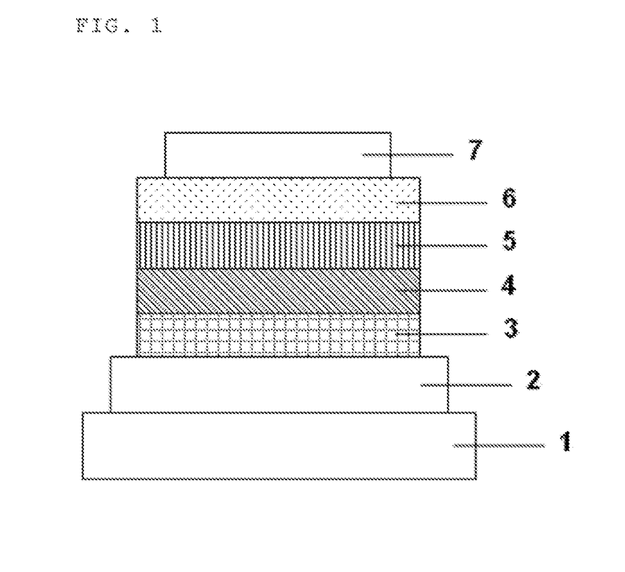
[0099]Each thin film was laminated on a glass substrate having formed thereon an anode formed of ITO having a thickness of 110 nm by a vacuum deposition method at a degree of vacuum of 4.0×10⁻⁵ Pa. First, HAT-CN serving as a hole-injecting layer was formed on ITO so as to have a thickness of 25 nm, and then NPD serving as a hole-transporting layer was formed so as to have a thickness of 30 nm. Next, HT-1 serving as an electron-blocking layer was formed so as to have a thickness of 10 nm. Then, the preliminary mixture HI serving as a host and Ir(ppy)3 serving as a light-emitting dopant were respectively co-deposited from different deposition sources to form a light-emitting layer having a thickness of 40 nm. At this time, the co-deposition was performed under such a deposition condition that the concentration of Ir(ppy)3 became 10 wt %. Next, ET-1 serving as an electron-transporting layer was formed so as to have a thickness of 20 nm. Further, lithium fluoride (LiF) serving as an ele...

examples 2 to 9

[0100]Organic EL devices were each produced in the same manner as in Example 1 except that in Example 1, any one of the preliminary mixtures H2 to H9 was used, as a host.

example 10

[0101]An organic EL device was produced in the same manner as in Example 3 except that in Example 3, after the formation of the light-emitting layer, Compound 1-8 serving as a hole-blocking layer was formed so as to have a thickness of 10 nm, and ET-1 serving as an electron-transporting layer was formed so as to have a thickness of 10 nm.


PUM

PropertyMeasurementUnit
temperatureaaaaaaaaaa
internal quantum efficiencyaaaaaaaaaa

Abstract

Provided is an organic EL device having a low driving voltage, high luminous efficiency, and a long lifetime. The organic EL device is an organic electroluminescent device including a light-emitting layer between an anode and a cathode opposite to each other, in which: the light-emitting layer contains a host material and a light-emitting dopant material; and the host material is a material obtained by mixing a first host selected from compounds in each of which a diphenyltriazinyl group is bonded to one nitrogen atom of an indolocarbazole ring and a phenyl group of the diphenyltriazinyl group is substituted with one or more phenyl groups, and a second host selected from compounds in each of which aromatic hydrocarbon groups are bonded to two nitrogen atoms of a biscarbazole ring and at least one of the aromatic hydrocarbon groups is a fused aromatic hydrocarbon group.

Description

TECHNICAL FIELD[0001]The present invention relates to an organic[0002]electroluminescent device (referred to as “organic EL device”).BACKGROUND ART[0003]When a voltage is applied to an organic EL device, a hole is injected from an anode into a light-emitting layer, and an electron is injected from a cathode into the layer, Then, in the light-emitting layer, the hole and the electron thus injected recombine to produce an exciton. At this time, according to the statistical law of electron spins, singlet excitons and triplet excitons are produced at a ratio of 1:3. The internal quantum efficiency of a fluorescent emission-type organic EL device using light emission by a singlet exciton is said to be at most 25%. Meanwhile, it has been known that the internal quantum efficiency of a phosphorescent emission-type organic EL device using light emission by a triplet exciton can be improved to 100% when intersystem crossing from a singlet exciton is efficiently performed.[0004]However, the l...

Claims


Application Information

Patent Timeline
Patent Type & Authority Applications(United States)
IPC IPC(8): H01L51/00H01L51/50C07D487/04C07D209/86C09K11/02
CPCH01L51/0067H01L51/5004C07D487/04C07D209/86C09K11/025H01L51/0072H01L51/0008H01L51/5012H01L51/5016H01L2251/5384H01L51/5096C09K11/06H10K50/00C09K2211/185C09K2211/1059H10K85/654H10K85/6572H10K50/12H10K50/11H10K50/18H10K71/16H10K2101/40H10K2101/10H10K2101/90
Inventor TADA, MASASHIKAI, TAKAHIROUEDA, TOKIKOOGAWA, JUNYANOGUCHI, KATSUHIDEHOTTA, MASANORI
Owner NIPPON STEEL CHEMICAL CO LTD
Why Eureka
Try Eureka