Inductor and dc-dc converter

a converter and direct current technology, applied in the direction of electric variable regulation, process and machine control, instruments, etc., can solve the problems of difficult heat caused in the inductor, the temperature of the inductor can rise, and the am radio installed, etc., to achieve the effect of reducing the size and inhibiting the nois

Active Publication Date: 2018-06-14
MURATA MFG CO LTD
View PDF15 Cites 31 Cited by
  • Summary
  • Abstract
  • Description
  • Claims
  • Application Information

AI Technical Summary

Benefits of technology

[0009]The present disclosure has been conceived to address such problems and is aimed at providing an inductor and a DC-DC converter, which, in the inductor including a core made from a metallic magnetic material, has noise inhibitory effect by a shielding member, ensures insulation and heat radiation between the shielding member and the core of the inductor while enabling size reduction.

Problems solved by technology

When, for example, the DC-DC converter is used as a power supply circuit of an electronic device in a car, noise radiated from an inductor of the DC-DC converter or the like can cause a problem for an AM radio installed in a car or the like.
According to the techniques disclosed in Japanese Unexamined Patent Application Publication No. 2002-334954, however, the resin film provided between the electronic component and the conductive film is not formed from a material having thermal conductivity.
Thus, when the electronic component is an inductor for example, it is difficult for the heat caused in the inductor to be radiated through the resin film and the temperature of the inductor can rise.
As a result, in connection with the design, the rise in self temperature of the inductor can lead to drop in rated current.

Method used


Image

  • Inductor and dc-dc converter
  • Inductor and dc-dc converter
  • Inductor and dc-dc converter

Examples


first embodiment

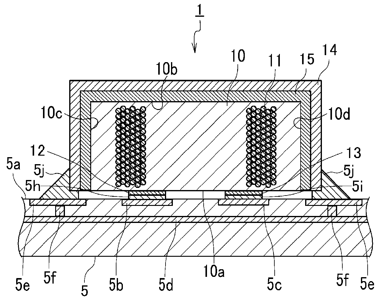
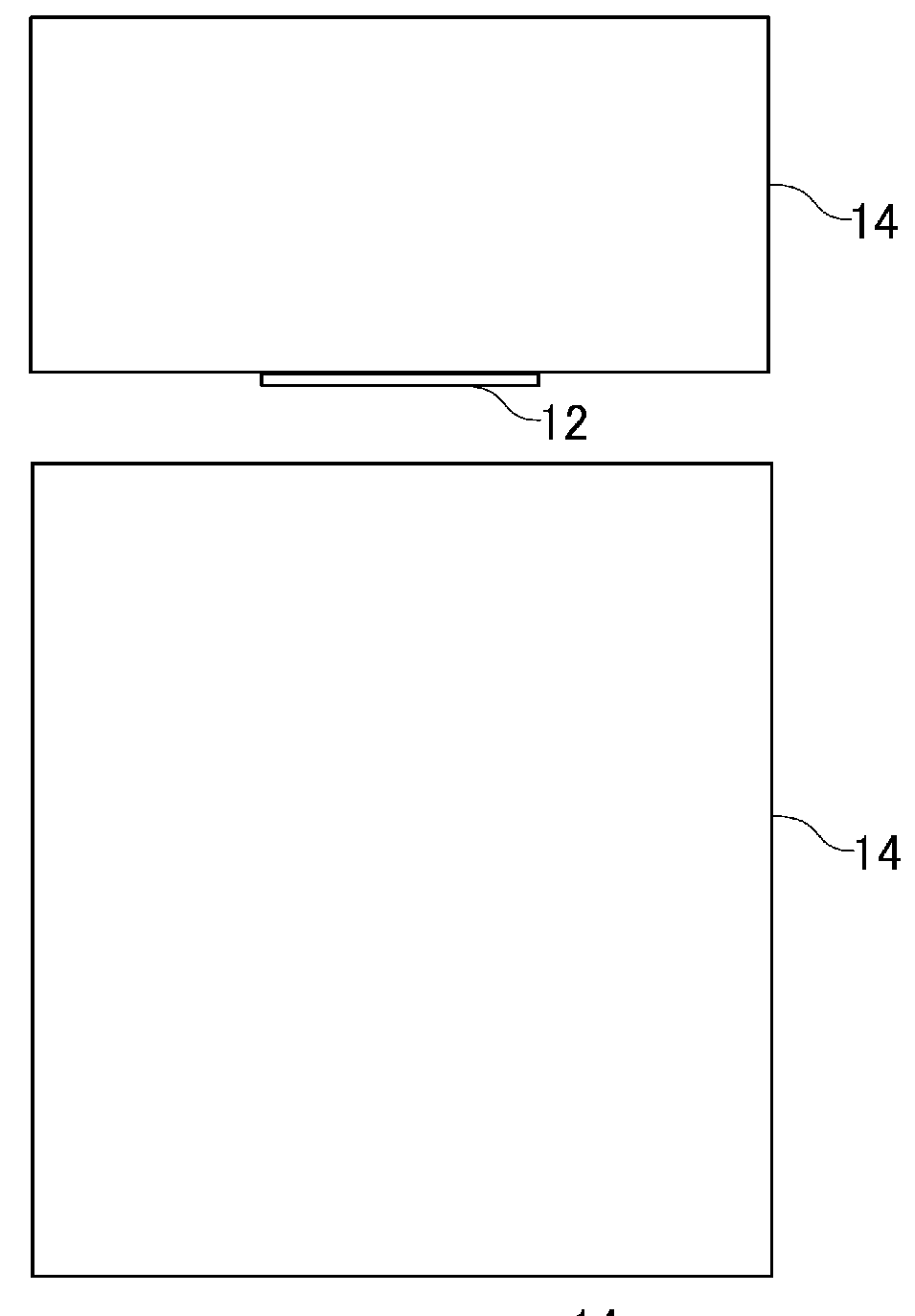
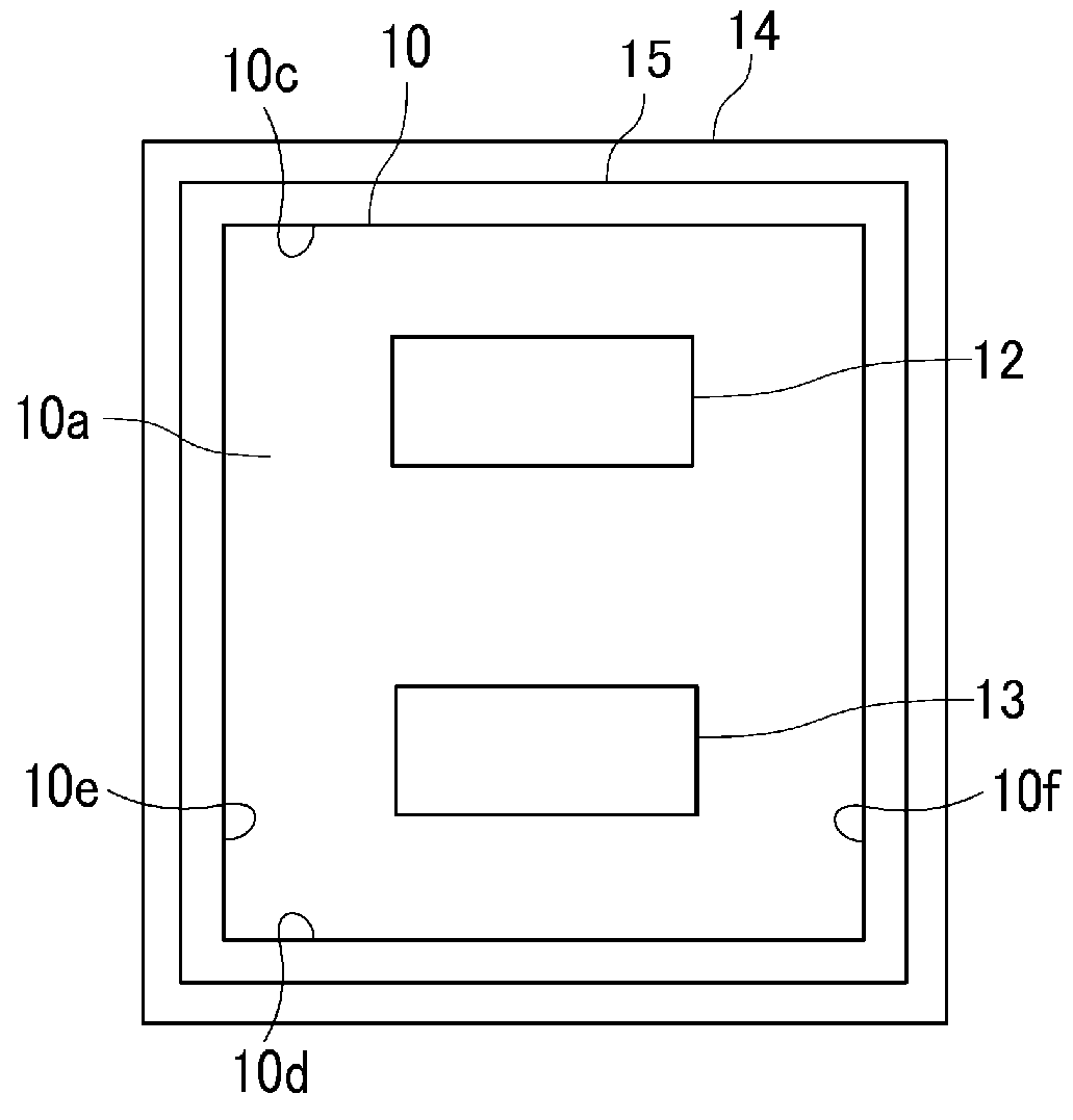
[0026]An inductor 1 according to the first embodiment is described by referring to FIGS. 1 to 3. FIG. 1 is a cross-sectional view that schematically illustrates a configuration of the inductor 1 according to the first embodiment. FIGS. 2A to 2C each schematically illustrate an external appearance of the inductor 1 according to the first embodiment, and FIG. 2A is a side view, FIG. 2B is a plan view, and FIG. 2C is a bottom view. FIG. 3 is a circuit diagram of a DC-DC converter 4 that includes the inductor 1 according to the first embodiment. FIG. 1 depicts the inductor 1 and part of a substrate 5 over which the inductor 1 is mounted.

[0027]The inductor 1 is a power inductor used as one of electronic components of the DC-DC converter 4. The DC-DC converter 4 that includes the inductor 1 is mounted over the substrate 5. The DC-DC converter 4 is described by referring to FIG. 3 before describing the inductor 1 in detail.

[0028]For example, the DC-DC converter 4 lowers (converts) a given ...

second embodiment

[0059]An inductor 2 according to the second embodiment is described by referring to FIGS. 4 and 5. FIG. 4 is a cross-sectional view that schematically illustrates a configuration of the inductor 2 according to the second embodiment. FIGS. 5A to 5C each schematically illustrate an external appearance of the inductor 2 according to the second embodiment, and FIG. 5A is a side view, FIG. 5B is a plan view, and FIG. 5C is a bottom view. FIG. 4 depicts cross sections of the inductor 2 and part of a substrate 5 over which the inductor 2 is mounted.

[0060]The inductor 2 is different from the inductor 1 according to the first embodiment in that the outer electrodes are provided on a side face of the core, and the shielding member and the insulating member are not provided on the side face. The inductor 2 includes a core 10 and a wire 11 similar to those of the inductor 1. The inductor 2 further includes a pair of outer electrodes 22 and 23, a shielding member 24, and an insulating member 25....


PUM

PropertyMeasurementUnit
thicknessaaaaaaaaaa
thicknessaaaaaaaaaa
voltageaaaaaaaaaa

Abstract

An inductor includes a core made from a metallic magnetic material, a wire wound around the core, a pair of outer electrodes coupled to respective end portions of the wire, a shielding member arranged so as to cover a top face and three or more side faces of the core, and an insulating member arranged between the core and the shielding member and having thermal conductivity. The thickness of the shielding member is set by applying the electric resistivity and permeability of the shielding member and the frequency of noise desired to be shielded to an expression for determining the depth of a skin of skin effect. The thickness of the insulating member is set according to the breakdown voltage of the insulating member and the voltage with which insulation is desired to be ensured under a use environment of the inductor.

Description

CROSS-REFERENCE TO RELATED APPLICATION[0001]This application claims benefit of priority to Japanese Patent Application No. 2016-238809, filed Dec. 8, 2016, the entire content of which is incorporated herein by reference.BACKGROUNDTechnical Field[0002]The present disclosure relates to an inductor and a direct-current to direct-current (DC-DC) converter including the inductor.Description of the Related Art[0003]A DC-DC converter includes a switching element, a diode, an inductor (a power inductor), and a smoothing capacitor for example, and lowers or boosts a given direct-current voltage to a desired direct-current voltage. When, for example, the DC-DC converter is used as a power supply circuit of an electronic device in a car, noise radiated from an inductor of the DC-DC converter or the like can cause a problem for an AM radio installed in a car or the like. To suppress such noise radiated from the inductor, for example, a shielding member that covers the inductor is used.[0004]As ...

Claims


Application Information

Patent Timeline
Patent Type & Authority Applications(United States)
IPC IPC(8): H01F27/36H02M3/156H02M1/14H01F27/24H01F27/28H01F27/29
CPCH01F27/36H02M3/156H02M1/143H01F27/24H01F27/2823H01F27/29H01F27/22H01F27/324H01F27/33H02M3/155H02M1/0064H01F27/363H01F17/04H02M1/44H01F27/292
Inventor TAKATSUJI, HIROYUKI
Owner MURATA MFG CO LTD
Why Eureka
Try Eureka