Charging system and method thereof

a charging system and charging system technology, applied in the direction of charging stations, electric vehicle charging technology, transportation and packaging, etc., can solve the problems of increasing the cost easy damage to the charging system, and inrush current damage to the internal electronic components of the charging system, so as to reduce the cost of fabricating the charging system, the effect of limiting the inrush current and enhancing the reliability of the charging system

Active Publication Date: 2018-06-14
DELTA ELECTRONICS (THAILAND) PUBLIC CO LTD
View PDF0 Cites 12 Cited by
  • Summary
  • Abstract
  • Description
  • Claims
  • Application Information

AI Technical Summary

Benefits of technology

[0007]An object of the present invention provides a charging system capable of limiting the inrush current. Since the inrush current is limited, the internal electronic components of the charging system are not damaged. Moreover, since the charging system is not equipped with the AC relay and the current-limiting resistor, the fabricating cost of the charging system is reduced and the reliability of the charging system is enhanced. Moreover, the charging system can be applied to the high power environment.

Problems solved by technology

The inrush current may damage the internal electronic components of the charging system.
Since the charging system is additionally equipped with the AC relay and the current-limiting resistor, the cost of the charging system is increased.
Moreover, since the AC relay has poor reliability and short life, the charging system is readily damaged.
In addition, the AC relay with high power has not been introduced into the market.
When the charging system is applied at a high power situation, the AC relay and the current-limiting resistor cannot be used.

Method used


Image

  • Charging system and method thereof
  • Charging system and method thereof
  • Charging system and method thereof

Examples


Embodiment Construction

[0021]The present invention will now be described more specifically with reference to the following embodiments. It is to be noted that the following descriptions of preferred embodiments of this invention are presented herein for purpose of illustration and description only. It is not intended to be exhaustive or to be limited to the precise form disclosed.

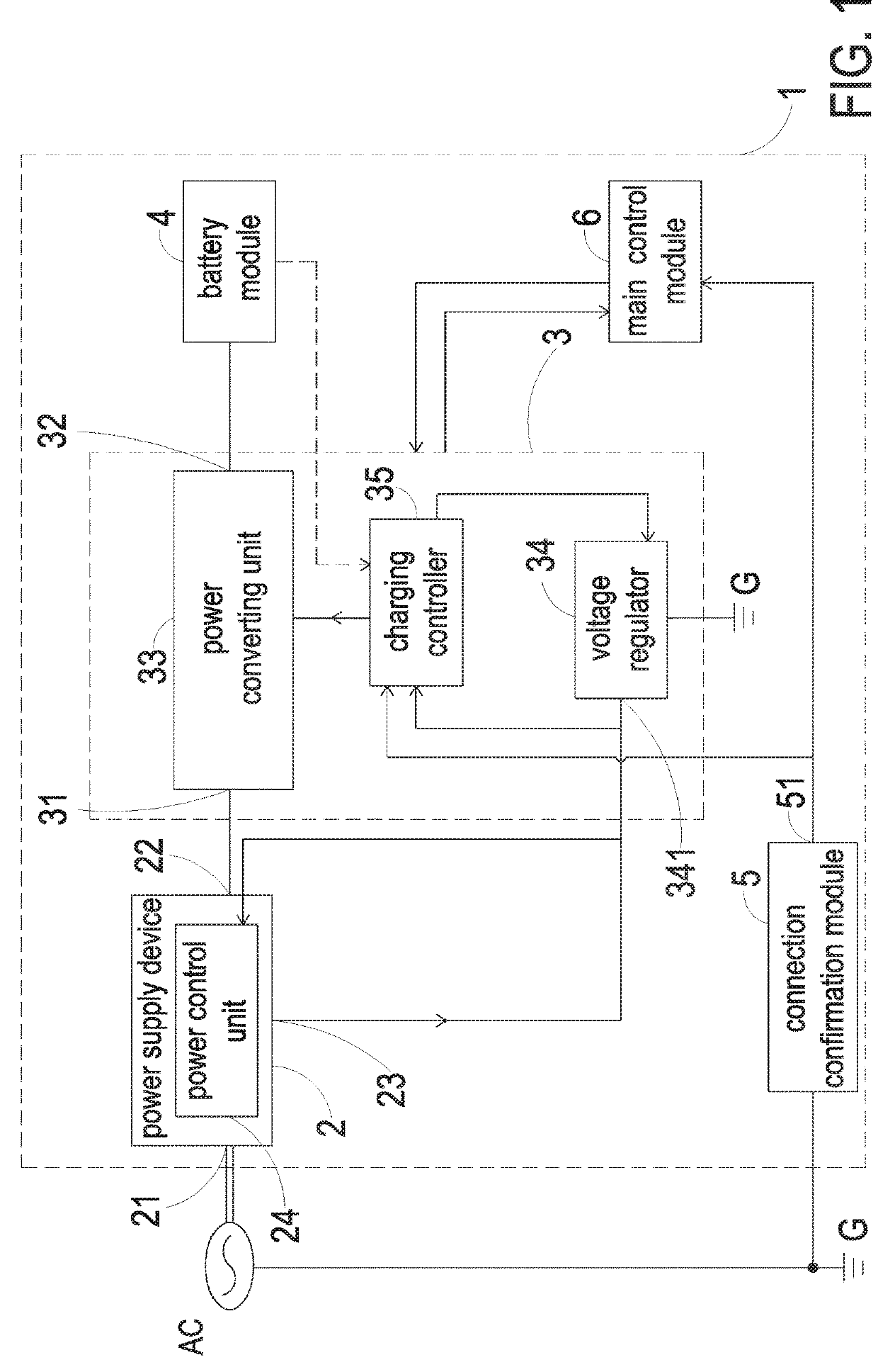
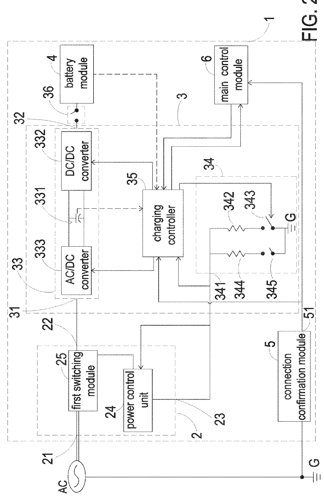
[0022]FIG. 1 schematically illustrates the architecture of a charging system according to an embodiment of the present invention. FIG. 2 is a schematic circuit diagram of the charging system of FIG. 1. As shown in FIG. 1, the charging system 1 is applied to an electric vehicle. The charging system 1 comprises a power supply device 2, a charging module 3, a battery module 4, a connection confirmation module 5 and a main control module 6.

[0023]An example of the power supply device 2 includes but not limited to an electric vehicle supply equipment (EVSE). The power supply device 2 is detachably connected with the charging module 3. ...


PUM


Abstract

A charging system and a method are provided. The charging system includes a power supply device, a charging module and a battery module. The charging module is detachably connected with the power supply device, and connected with the battery module. The charging module includes a power converting unit, a voltage regulator and a charging controller. When the power supply device and the charging module are connected with each other, the power converting unit of the charging module is in the backward direction and uses the electric power of the battery module to pre-charge a bus capacitor. If the voltage of the bus capacitor is higher than or equal to a first threshold value because of pre-charge, the voltage of an adjusting terminal of the charging module is adjusted. Consequently, the charging system is in a normal working mode.

Description

FIELD OF THE INVENTION[0001]The present invention relates to a charging system and a method, and more particularly to a charging system and a method for pre-charging a bus capacitor through a battery module when the charging system starts up.BACKGROUND OF THE INVENTION[0002]With increasing development of science and technology, charging systems are widely used in many fields. For example, charging systems are used for charging electric vehicles.[0003]Generally, the charging system comprises a bus capacitor. When the charging system starts up to receive the input AC power, a large transient current is generated to charge the bus capacitor. The large transient current is also referred as an inrush current. The inrush current may damage the internal electronic components of the charging system.[0004]For solving the above drawbacks, the conventional charging system is further equipped with an AC relay and a current-limiting resistor. The AC relay and the current-limiting resistor are co...

Claims


Application Information

Patent Timeline
Patent Type & Authority Applications(United States)
IPC IPC(8): H02J7/34H02J7/00
CPCH02J7/345H02J7/0052H02J7/027H02M1/4225H02M1/36H02J7/0036B60L2270/20H02M3/33584B60L53/20H02J2310/48Y02T10/70Y02T10/92Y02T10/7072Y02T90/14H02M1/007H02M1/0085H02J7/00Y02B70/10
Inventor SUN, HAOZHANG, JINFAMENG, YUEYONGLI, SHUANGGANG
Owner DELTA ELECTRONICS (THAILAND) PUBLIC CO LTD
Why Eureka
Try Eureka