Multi-functional flap used as a back-flow flap

Inactive Publication Date: 2018-06-21
ROHM DIETER
View PDF9 Cites 10 Cited by
  • Summary
  • Abstract
  • Description
  • Claims
  • Application Information

AI Technical Summary

Benefits of technology

[0027]b) energy generating systems, by way of higher lift in high-lift situations at a low fluid speed, and at high fluid/wind speeds by lift reduction/a braking effect, as a result of higher availability (for example shorter shutdown times due to strong winds and the resulting improved annual energy output) of the energy generating system.
[0028]A further object of the invention is, optionally simultaneously, to provide a safety means on a wing with which the susceptibility of the wing to gusts, in particular in a strong wind, is reduced by an actively activated back-flow flap having for example a slowly increasing braking effect. Said flap can also react rapidly when required, in such a way

Problems solved by technology

(It has been found that for example the wing deformation increases over the course of the service life, but this needs to remain within a limited range).
A drawback of these embodiments is the short service life of the materials used under actual weather conditions such as ice, rain, sand, UV radiation.
Moreover, in this context the low mechanical stability under conditions of use, such as strong gusts and winds, and the potentially required cleaning of an aerofoil of an aeroplane are disadvantageous.
Considerable hysteresis in raising and lowering the flaps was found, and this has considerable drawbacks for optimum lift during operation.
In reality, fluttering of the back-flow flap is a drawback, and can also produce noise and is problematic for the service life.
A drawback in this context is the use of movable plain flaps, which for one thing have to be highly resilient and are high-maintenance (experience from aircraft constr

Method used


Image

  • Multi-functional flap used as a back-flow flap
  • Multi-functional flap used as a back-flow flap
  • Multi-functional flap used as a back-flow flap

Examples


Example

LIST OF REFERENCE NUMERALS FOR FIGS. 1 TO 25 FOR A BACK-FLOW FLAP

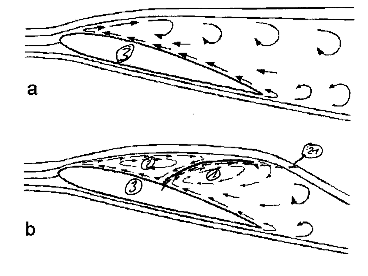
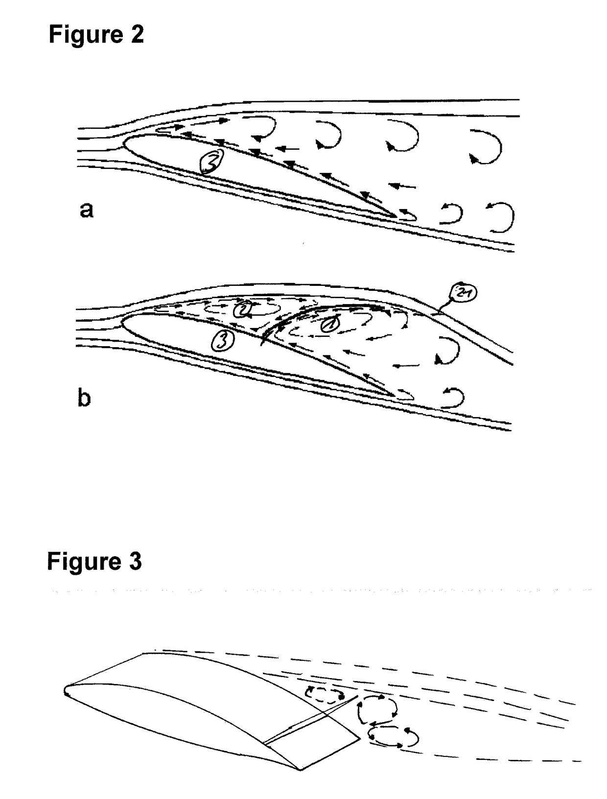
[0374]1. Trailing edge separation vortex

2. Flap separation vortex

3. Aerodynamic / hydrodynamic body / wing / profile

4. Prior art back-flow flaps (lift element)

5. Boundary component

6. Trailing profile edge

7. Joint

[0375]8. Triangular back-flow flap (flap / lift element)

9. Arc-shaped back-flow flap (flap / lift element)

10. Parallelogram back-flow flap (flap / lift element)

11. Resilient material / hinge

12. Springy material

13. Hose

[0376]14. Fluid / gas filling region

15. Hydraulic / pneumatic cylinder or other actuator

16. Support face / connection point with respect to the wing

17. Angle of attack α of the wing

18. Fluid / gas connection

19. Point of the greatest profile thickness

20. Flap transition

21. Flap region boundary

22. Actuator element

23. Base element

24. Lightning protection system

25. Noise-reducing lift element and / or base element

26. Means for limiting the excursion

27. Fixing means

28. Mass inertia element

29. Lever

[0377]30. Centre of rotation...


PUM


Abstract

The invention relates to a device of a safety system and/or resource and energy-efficiency improvement system for influencing the flow around an aero- or hydrodynamic body, preferably an aerofoil, according to the principle of a back-flow flap, characterized in that: said device, together with the aero- or hydrodynamic body, in particular aerofoil, form at least a partial shift of the delimitation of the flap region by means of the back-flow flap and the delimiting component thereof when the back-flow flap is partially and/or completely raised, thus influencing the trailing edge separation vortex/vortices and/or the flap separation vortex/vortices; and in that the delimitation of the flap region shifts completely up to or beyond the profile trailing edge, or shifts only to a section in front of the profile trailing edge. The delimitation component is movably connected to the aerofoil by means of a basic element and is preferably permanently secured and/or releasably secured for maintenance purposes, thus ensuring a long service life for the rotor blade and/or wind turbine and/or flap system, preferably >5 years, particularly preferably >10 years, and most particularly preferably >=20 years, and/or thus optionally allowing simple removal/replacement.

Description

CROSS-REFERENCE TO RELATED APPLICATIONS[0001]This application is a Section 371 National Stage Application of International Application No. PCT / DE2016 / 100029, filed on 24 Jan. 2016, which published as WO 2016 / 116102 on 28 Jul. 2016, which claims priority to German Patent Application Nos. 20 2015 000 665.5, filed on 24 Jan. 2015; 10 2015 113 374.4, filed on 13 Aug. 2015; and 10 2015 114 617.7, filed on 1 Sep. 2015, the contents of which are hereby incorporated by reference in their entirety.DESCRIPTIONTechnical Field of the Invention[0002]Birds naturally have back-flow flaps.[0003]Accordingly, the mode of operation of these flaps can be interpreted as follows:[0004]Raising the flap causes a stationary flap vortex to form in front of it, the flow direction of said vortex pointing from back to front on the upper wing face. The flap vortex extends forwards almost into the nose region. It thus in effect fills the triangular region between the upper wing face, the upper flap face and the s...

Claims


Application Information

Patent Timeline
IPC IPC(8): F03D7/02B64C9/02B64C3/46B64C9/18B64C9/20F03B3/12F03D1/06F03D80/30F15D1/10
CPCF03D7/0232B64C9/02F03D7/0252B64C3/46B64C9/18B64C9/20F03B3/123F03D1/0675F03D1/0633F03D80/30F15D1/10F05B2210/16F05B2240/311F05B2240/98F05B2250/183F05B2260/507F05B2260/901F05B2260/964F05B2270/402F05B2270/404B64C9/00B64C23/00F05B2240/31F05B2240/305F05B2240/3052Y02E10/20Y02E10/72Y02T50/30
Inventor ROHM, DIETER
Owner ROHM DIETER
Why Eureka
Try Eureka