
Differential Colpitts Voltage-Controlled Oscillator

a voltage-controlled oscillator and differential colpitts technology, applied in the field of voltage oscillators, can solve the problems of additional power consumption, and achieve the effects of reducing the power consumption improving phase noise cancellation performance, and improving the effective impulse sensitivity function of the differential colpitts voltage-controlled oscillator

Active Publication Date: 2018-06-21
KOREA ADVANCED INST OF SCI & TECH
View PDF2 Cites 9 Cited by
  • Summary
  • Abstract
  • Description
  • Claims
  • Application Information

AI Technical Summary

Benefits of technology

The patent describes a new type of circuit that generates high-quality clock signals for electronic devices. It includes a feedback circuit, a negative resistance circuit, a resonance circuit, and a phase noise reduction circuit. These circuits work together to improve the stability and accuracy of the clock signals, while also reducing power consumption. The technical effect of this invention is to provide a more efficient and effective solution for generating high-quality clock signals.

Problems solved by technology

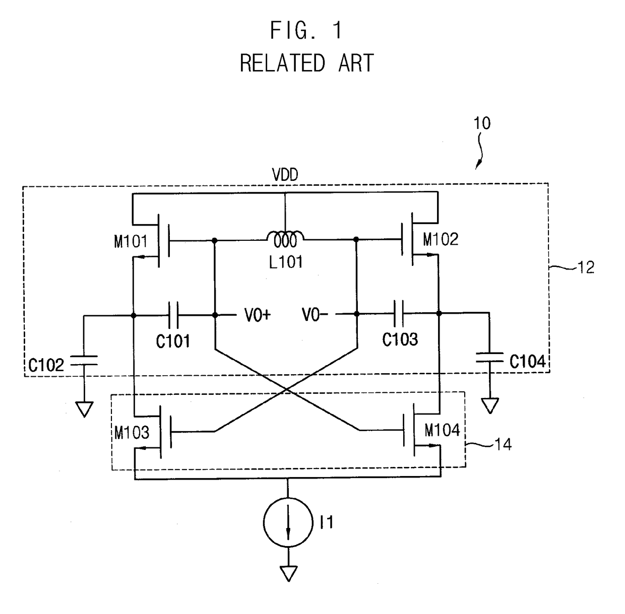
However, oscillating start conditions of the Colpitts oscillator are not as good as the LC cross-coupled oscillator such that additional power consumption is required.

Method used


Image

  • Differential Colpitts Voltage-Controlled Oscillator
  • Differential Colpitts Voltage-Controlled Oscillator
  • Differential Colpitts Voltage-Controlled Oscillator

Examples


Embodiment Construction

[0022]Exemplary embodiments will be described more fully hereinafter with reference to the accompanying drawings, in which various embodiments are shown.

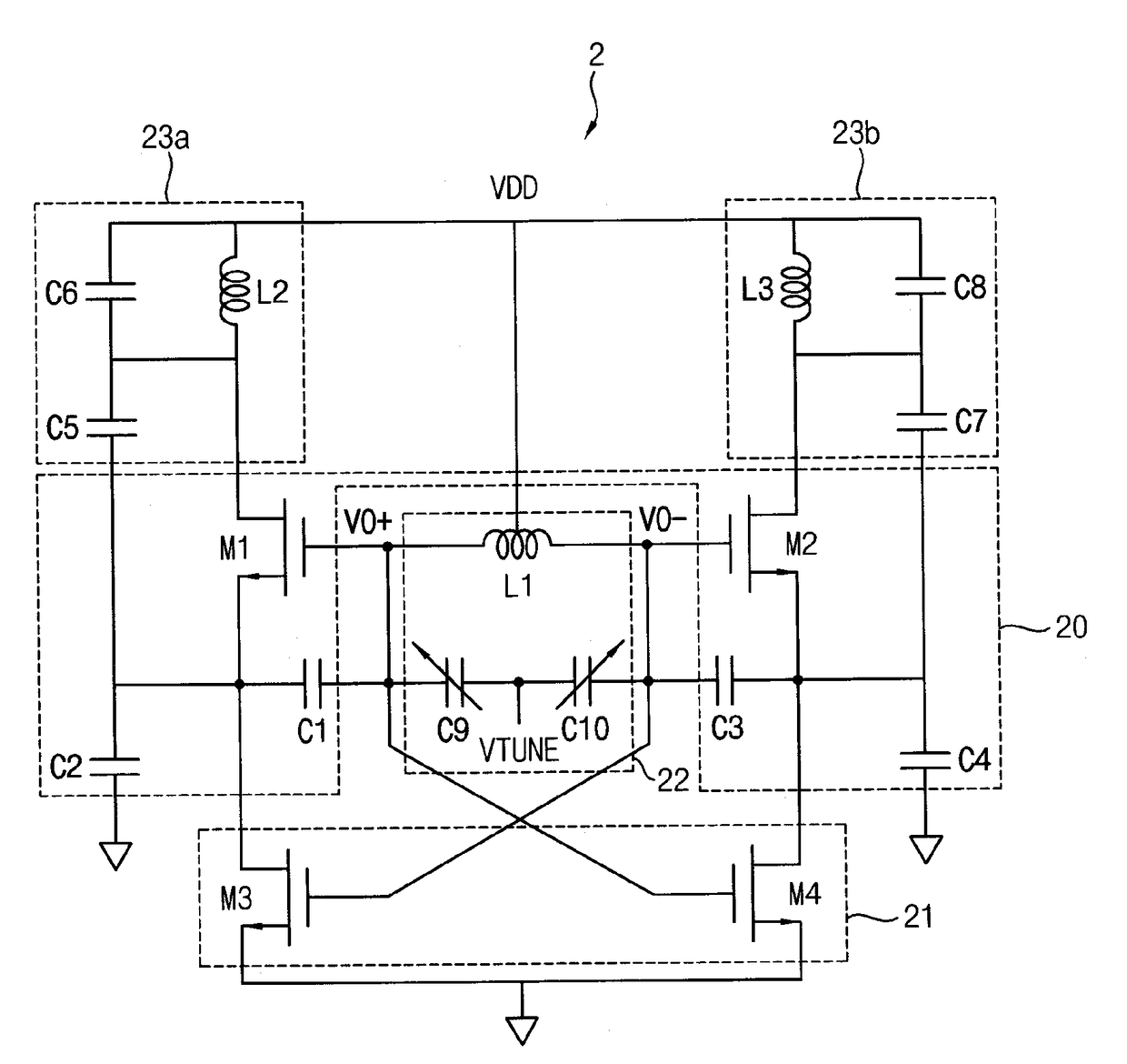
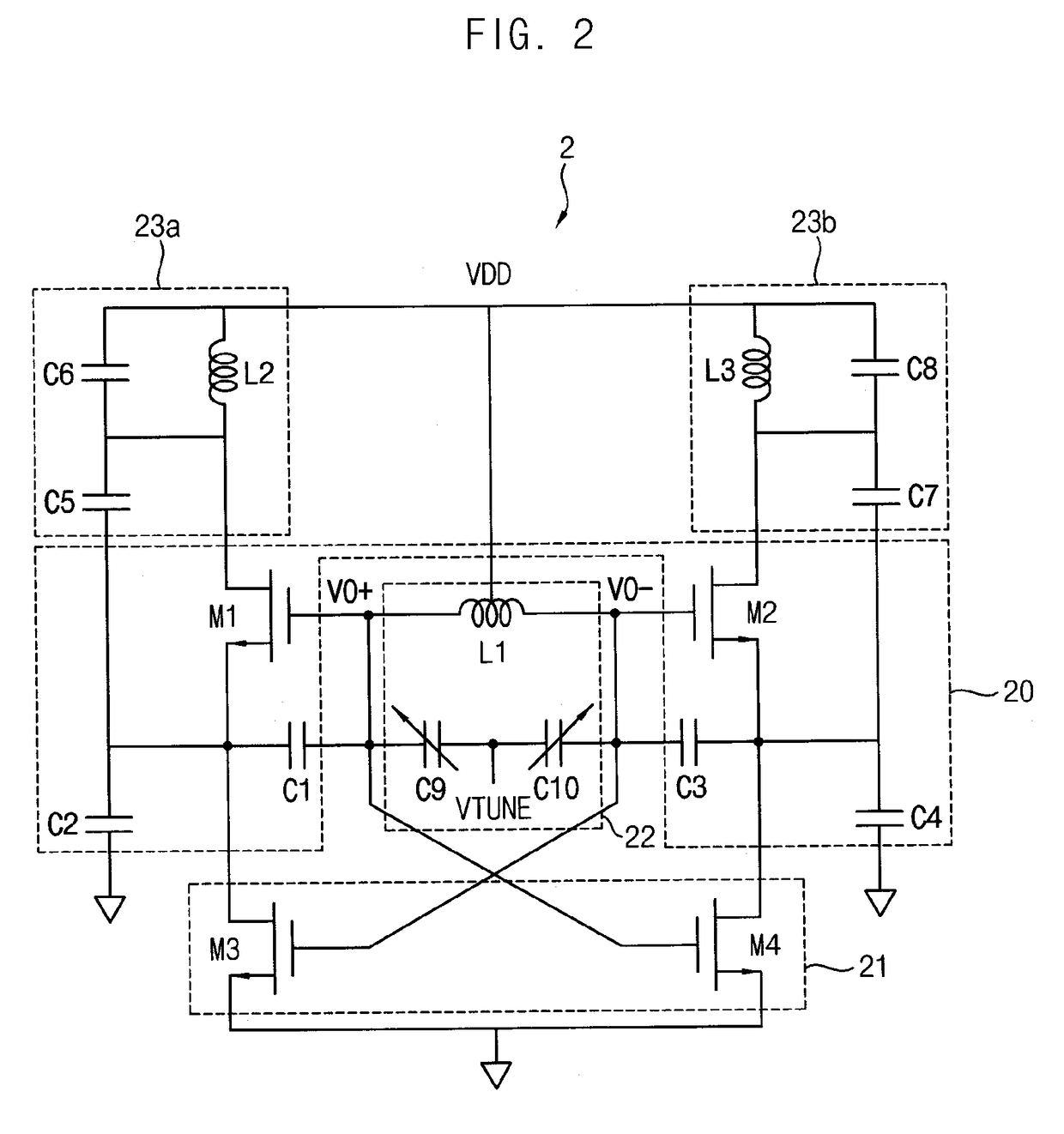
[0023]FIG. 2 is a circuit diagram of a differential Colpitts voltage-controlled oscillator according to example embodiments. FIGS. 3A and 3B are timing diagrams illustrating examples of which operation regions of first and second switching transistors are limited by a phase noise reduction circuit included in the differential Colpitts voltage-controlled oscillator of FIG. 2.

[0024]Referring to FIGS. 2 to 3B, the differential Colpitts voltage-controlled oscillator 2 may include a feedback circuit 20 constituting a Colpitts oscillator structure, a negative resistance circuit 21, a resonance circuit 22 (e.g., a tank circuit) including a first inductor L1 and a pair of variable capacitors C9 and C10 that are connected in parallel with the first inductor L1, and a phase noise reduction circuit 23a and 23b.

[0025]The feedback circuit20 may...


PUM


Abstract

A differential Colpitts voltage-controlled oscillator according to example embodiments includes a feedback circuit constituting a Colpitts oscillator structure, a negative resistance circuit including a first negative resistance transistor and a second negative resistance transistor cross-coupled to each other and connected to the feedback circuit, a resonance circuit including a first inductor and a variable capacitor connected to both ends of the first inductor to generate differential output signals base on outputs of the feedback circuit, and a phase noise reduction circuit coupled to the feedback circuit to remove phase noise.

Description

CROSS REFERENCE TO RELATED APPLICATION[0001]This application claims priority to and the benefit of Korean Patent Application No. 10-2016-0171339, filed on Dec. 15, 2016 in the Korean Intellectual Property Office (KIPO), the disclosure of which is hereby incorporated by reference herein in its entirety.BACKGROUND1. Field[0002]Example embodiments of the inventive concept relate to voltage oscillators. More particularly, example embodiments of the inventive concept relate to differential Colpitts voltage-controlled oscillators having transconductance amplification structure.2. Discussion of Related Art[0003]With the development of Complementary Metal-Oxide Semiconductor (CMOS) transistor process techniques, very high data transmission of tens of gigabits per second (Gbps) has become possible in wireless communications. In order to implement the wireless communication system employing such a high data rate and a higher-order modulation, a high-performance voltage-controlled oscillator w...

Claims


Application Information

Patent Timeline
IPC IPC(8): H03B7/06H03B5/12
CPCH03B7/06H03B5/1212H03B2200/0008H03B5/1243H03B2200/009H03B5/1228
Inventor PARK, CHUL-SOONKANG, DONG-MIN
Owner KOREA ADVANCED INST OF SCI & TECH
Learn More