Gas slab laser

a laser and gas slab technology, applied in gas laser construction details, laser details, electrical equipment, etc., can solve the problems of limited laser output power, extensive loss, laser deterioration, etc., and achieve the effect of reducing the electrode gap and high power load

Active Publication Date: 2018-07-05
STATE OF ISRAEL - SOREQ NUCLEAR RES CENT
View PDF4 Cites 2 Cited by
  • Summary
  • Abstract
  • Description
  • Claims
  • Application Information

AI Technical Summary

Benefits of technology

[0012]The present invention relates to a method and apparatus for achieving high power load per unit in the electrode area in slab lasers by reducing the electrode gap. In one embodiment, the method includes a combination of high frequency discharge excitation in the MW range and a special optical waveguide at 10.6 μm wavelength, based on a one-dimensional (1D) photonics band-gap waveguide or a waveguide composed of dielectric walls made of materials that have a refractive index lower than 1, which is approximately the refractive index of the laser plasma. In one embodiment, these materials are transparent to the MW wavelength and are not affected by the laser plasma (plasma heat damages, possible degradation due to plasma emission of deleterious particles and photons). Non-limiting examples of such materials are ceramics such as aluminum oxide (Al2O3) or beryllium oxide (BeO).

Problems solved by technology

The laser output power is limited by the allowed RF power load in the discharge per unit area.
Exceeding the power load limitation for a given electrodes spacing, results in laser deterioration, due to thermal deleterious effects.
Therefore, reducing the electrodes spacing will result in an extensive loss and laser efficiency deterioration.
Attempts have been made to excite gas lasers with microwave (MW) discharges, but the waveguide-loss-limited electrode spacing, on the order of 1-2 mm, did not allow for stable CW microwave discharges (due to the narrow depletion layers) and pulsed operation was utilized for achieving stable plasma.
As mentioned before, reducing the electrode spacing in the traditional leaky waveguide, as shown in FIGS. 1A-1C, will result in extensive waveguide losses.
The leaky waveguide losses amount to over 90% loss of power per 1 m of 10.6 μm light propagation through the waveguide.

Method used


Image

  • Gas slab laser
  • Gas slab laser
  • Gas slab laser

Examples


Embodiment Construction

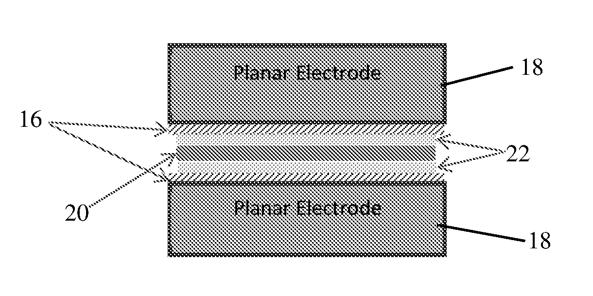
[0022]Reference is now made to FIGS. 3A-3B, which illustrate a bandgap structured waveguide 10 for a gas slab laser, constructed and operative in accordance with an embodiment of the invention, made of an aluminum oxide / germanium (Al2O3 / Ge) planar structure.

[0023]The waveguide 10 includes dielectric electrodes 12 that have a photonic band-gap structure, which prohibits (at the selected wavelength, relevant for the laser operation) light propagation in the dielectric electrodes material. In a particular embodiment, dielectric electrodes 12 include spatially alternating layers of two different materials—Al2O3 and Ge (aluminum oxide and germanium)—have been utilized (with refracting indices of 0.67-i0.04 and 4, respectively) (FIG. 3A) for λ=10.6 μm wave propagation. A layer width of λ / (4−n) was chosen for each material type, where n stands for the refractive index of the relevant material. The bandgap structure confines a gap 14, such as a one dimensional 250 μm gap, in which the CO2 l...


PUM


Abstract

A microwave excited gas slab laser comprising a waveguide wherein the electrodes are covered with multi-layered stripes either forming a photonic band-gap or having a refractive index lower than 1.

Description

FIELD OF THE INVENTION[0001]The present invention relates to a structure and methods for achieving a higher RF power load in diffusion-cooled gas slab laser plasma.BACKGROUND OF THE INVENTION[0002]Diffusion-cooled, gas-discharge slab lasers are characterized by output power of several watts per unit area of discharge. Slab gas lasers based on large area electrodes confining a CO2 laser mixture, driven by radio-frequency (RF) power supplies (FIG. 1A), are currently delivering over three kilowatts of power with excellent beam quality, due to a special optical resonator, allowing for maximum exploitation of the discharge gain volume for a single mode beam amplification.[0003]In order to maximize the discharge cooling, which is of prime importance for electrically excited gas lasers, the planar discharge width is of the order of the planar electrodes gap, which is typically 1-2 mm. In addition, the discharge electrodes are used as an optical waveguide for the amplified laser beam. Stabi...

Claims


Application Information

Patent Timeline
Patent Type & Authority Applications(United States)
IPC IPC(8): H01S3/038H01S3/03H01S3/223H01S3/097
CPCH01S3/0388H01S3/0315H01S3/2232H01S3/097
Inventor SINTOV, YOAVZALEVSKI, ZEEV
Owner STATE OF ISRAEL - SOREQ NUCLEAR RES CENT
Why Eureka
Try Eureka