
Heat-dissipating semiconductor assembly

Inactive Publication Date: 2018-07-05
LUXNET CORP
View PDF3 Cites 1 Cited by
  • Summary
  • Abstract
  • Description
  • Claims
  • Application Information

AI Technical Summary

Benefits of technology

The invention aims to solve the problem of poor heat dissipation in laser diodes, which causes low light output power and short lifespan in the prior art. The solution involves depositing the laser diode on a heat-dissipating substrate and reducing the active area of the diode to shorten the heat conduction path. Additionally, a groove is formed on the substrate to align with the ridge of the diode, preventing the substrate from damaging the diode during operation. These features improve the laser diode's heat dissipation and light output, leading to its better performance and durability.

Problems solved by technology

When operating, a laser diode unavoidably generates a great quantity of heat.
If the heat is not released timely, the junction of the laser diode can become hot and this can jeopardize the device's performance and service life, in turn blighting the device's reliability.
However, the contacting area between the metal wire and the electrodes of the laser diode is too small and the distance from the light-emitting area of the laser diode to the heat-dissipating substrate is too far to provide timely heat dissipation, thus not able to ensure the device's performance and service life.

Method used


Image

  • Heat-dissipating semiconductor assembly
  • Heat-dissipating semiconductor assembly
  • Heat-dissipating semiconductor assembly

Examples


first embodiment

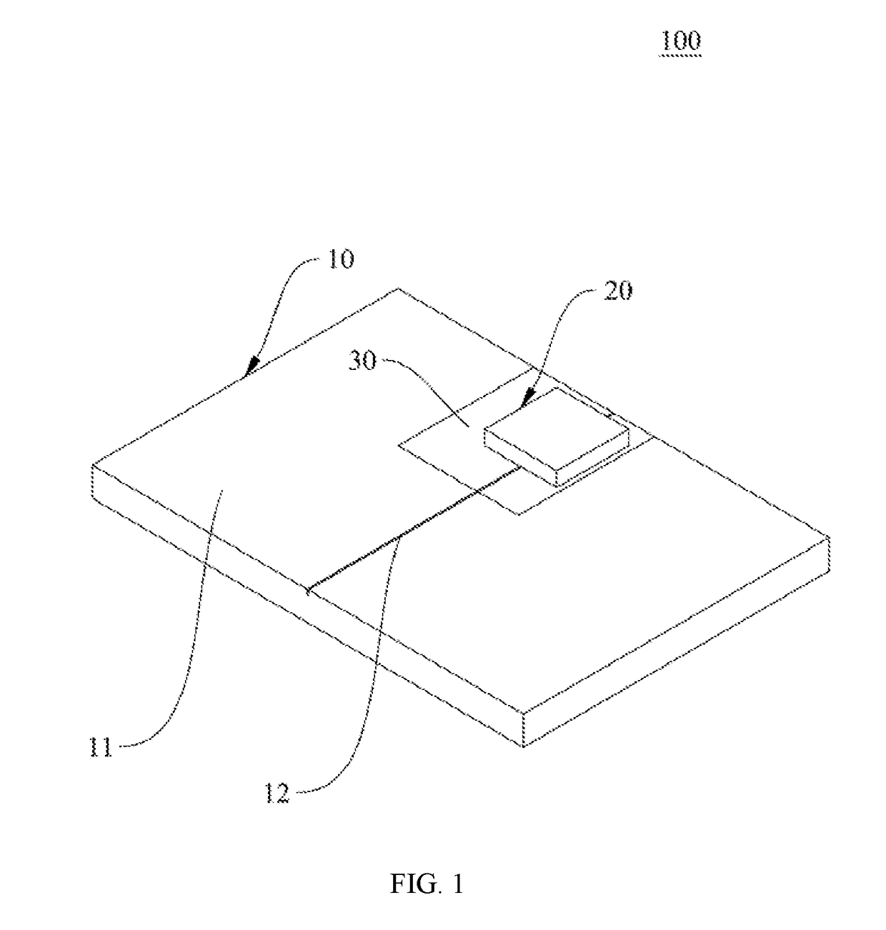
[0027]Please first refer to FIG. 1 for a perspective schematic view of the present invention.

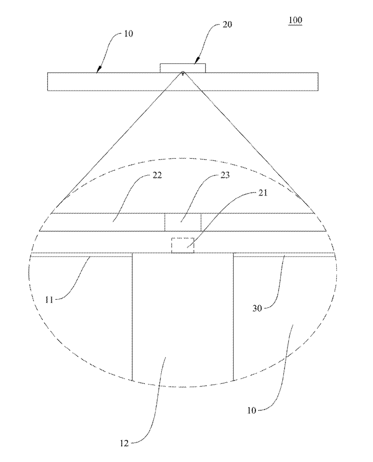
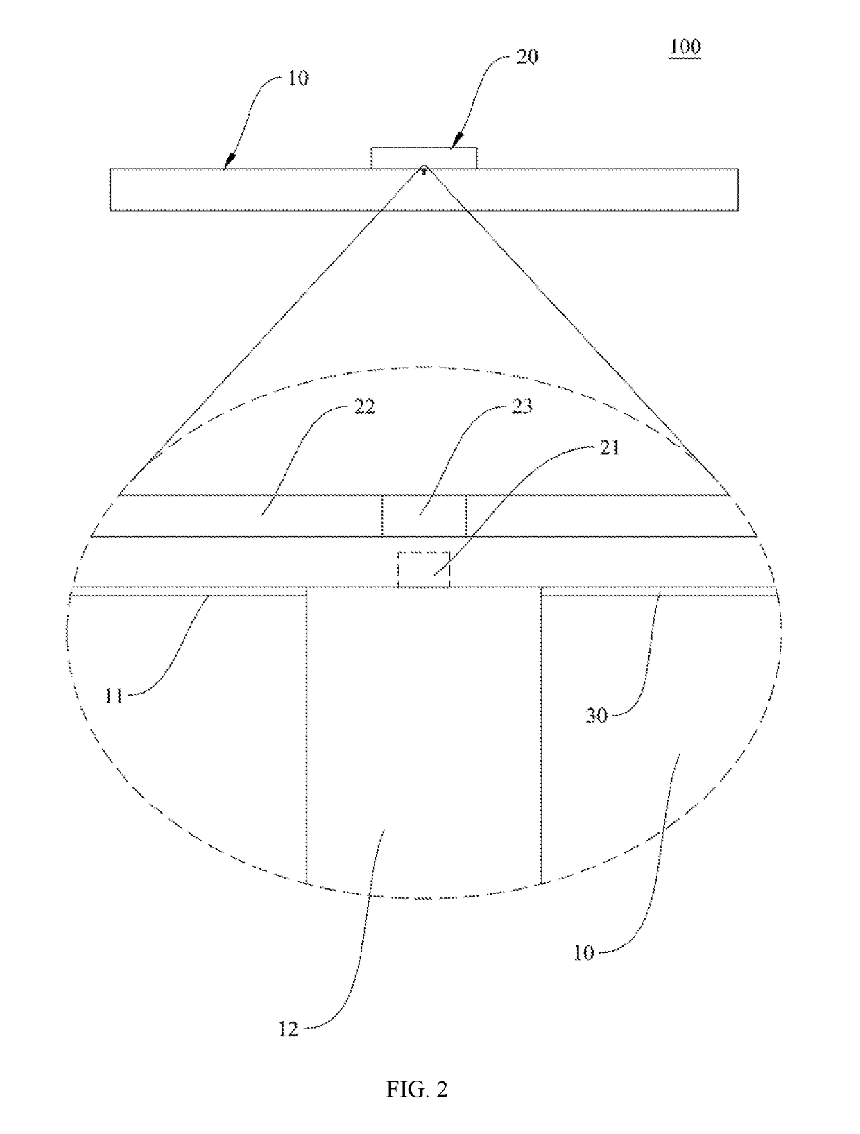
[0028]The present embodiment provides a heat-dissipating semiconductor assembly. The heat-dissipating semiconductor assembly 100 primarily comprises a heat-dissipating substrate 10 and an edge emitting laser diode 20. The heat-dissipating substrate 10 has its one side formed with a flat surface 11, a metal solder layer 30, and a groove 12 formed on the flat surface 11. The heat-dissipating substrate 10 can be a ceramic board that features high thermal conductivity, low thermal resistance, long service life, and good thermal endurance. With high thermal conductivity and good thermal endurance, the ceramic board can effectively transfer heat for heat dissipation. Particularly, the heat-dissipating substrate 10 can be made of a ceramic material containing aluminum nitride (AlN), silicon carbide (SiC), or aluminum oxide (Al2O3) or a composite material composed of the foregoing materials, and the...

second embodiment

[0040]Please refer to FIG. 4 for a cross-sectional view of the present invention.

[0041]The edge emitting laser diode 50 comprises an active area 52 and a ridge 51 deposited on one side of a light-emitting area 53 of the active area 52. Particularly, the ridge 51 can be a P-type semiconductor, and the active area 52 can be an area between P and N, which depends on the type of the edge emitting laser diode 50 used. An electrode layer (not shown in drawing) is optionally formed on the bottom side of the ridge 51 to cover the outside of the ridge 51. The electrode layer can extend in both sides to the upper side of the metal solder layer 60. The edge emitting laser diode 50 is mounted on the metal solder layer 60. By lowering the active area 52 of the edge emitting laser diode 50, the active area 52 of the edge emitting laser diode 50 is drawn closer to one side of the heat-dissipating substrate 40. The edge emitting laser diode 50 has its optical output direction parallel to the flat s...


PUM


Abstract

The invention provides a heat-dissipating semiconductor assembly, comprising: a heat-dissipating substrate, a metal solder layer, and an edge emitting laser diode. The heat-dissipating substrate has one side formed with a flat surface for mounting the edge emitting laser diode. The edge emitting laser diode is mounted on the metal solder layer, and by lowering the active area of the edge emitting laser diode, the active area of the edge emitting laser diode is drawn close to one side of the heat-dissipating substrate. The edge emitting laser diode has an optical output direction parallel to the flat surface of the heat-dissipating substrate, and the heat-dissipating substrate and / or the metal solder layer have a groove. The ridge of the edge emitting laser diode is aligned with an opening formed in the groove of the heat-dissipating substrate, thereby preventing the heat-dissipating substrate and metal solder layer from contacting the ridge of the edge emitting laser diode.

Description

BACKGROUND OF THE INVENTION1. Technical Field[0001]The present invention relates a heat-dissipating semiconductor assembly, more particularly to a heat-dissipating substrate with the groove form for high power semiconductor assembly.2. Description of Related Art[0002]As optical communication devices become more performative, they have been developed to be more compact, more capable, and maturer in terms of power, data transfer rate, thermal stability as well as voltage endurance. Laser diodes represent one of the most extensively used segments. When operating, a laser diode unavoidably generates a great quantity of heat. If the heat is not released timely, the junction of the laser diode can become hot and this can jeopardize the device's performance and service life, in turn blighting the device's reliability. Hence, for ensuring reliability, it is necessary to improve the device's heat dissipation.[0003]In the field of optical communication, heat dissipation for laser diodes have ...

Claims


Application Information

Patent Timeline
IPC IPC(8): H01S5/024H01S5/022H01S5/023H01S5/0233
CPCH01S5/02469H01S5/22H01S5/4031H01S5/02236H01S5/02476H01S5/0234H01S5/0237H01S5/023H01S5/0233H01S5/0235
Inventor LIN, HSING-YENLAW, PI-CHENGHUANG, PO-CHAOLIU, BO-WEIDENG, YA-HSINSU, HUA-HSIN
Owner LUXNET CORP
Learn More