Symbiotic reverse osmosis for maximizing desalinated water recovery from saline waters and brines

a technology of desalinated water and saline water, applied in the field of symbiotic reverse osmosis system, can solve the problems of unsuitable performance, unsatisfactory performance, and all these applications that are functionally still limited, and achieve the effect of remixing seawater with desalinated water

Active Publication Date: 2018-07-12
KELADA MAHER ISAAC
View PDF0 Cites 1 Cited by
  • Summary
  • Abstract
  • Description
  • Claims
  • Application Information

AI Technical Summary

Problems solved by technology

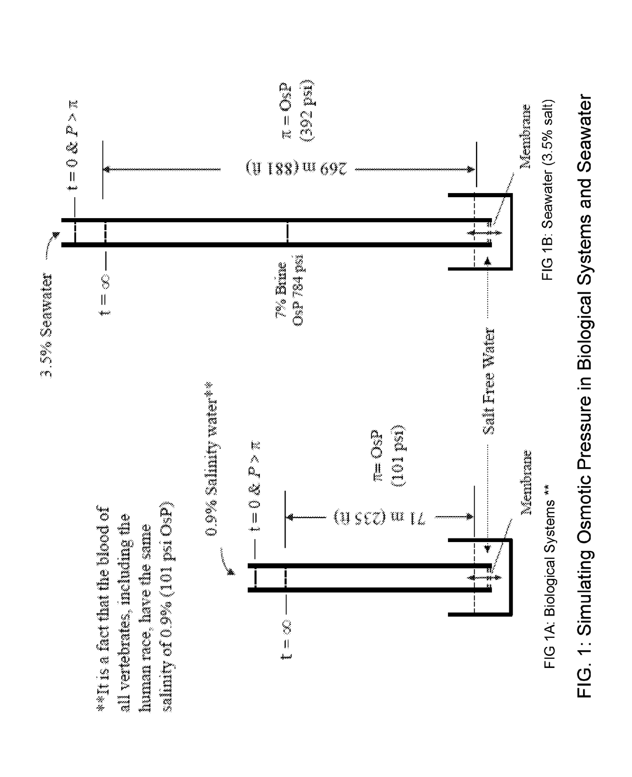
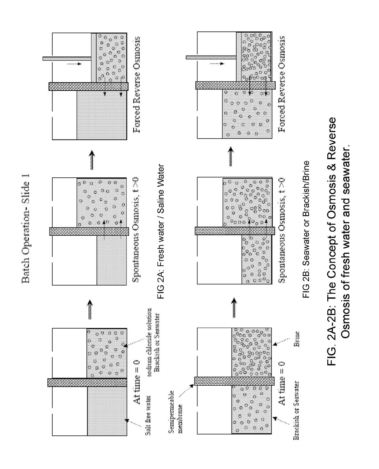
However, all of these applications are functionally still limited by seawater salinity of 3.5%
Spiral wound and hollow fiber membranes are heavily used today in seawater desalination, but these membranes, due to their relatively low mechanical integrity, their compacted assembly and excessive fouling are unsuitable to meet the stringent performance of the aforementioned two objectives.
Eventually, this membrane fails causing remixing seawater with desalinated water.
Therefore, reverse osmosis processes, particularly for high salinity are pressure demanding technologies, requiring the use of multi-stage pumps and pressure vessels.
Further, the current commercial semipermeable membrane maximum operating limit is at or about 7% salinity, which prevents any further development of processes that can make advantage of higher salinity domains such as Great Salt Lake, USA of 24%, or the Dead Sea, Israel of 36% and many others sites worldwide.
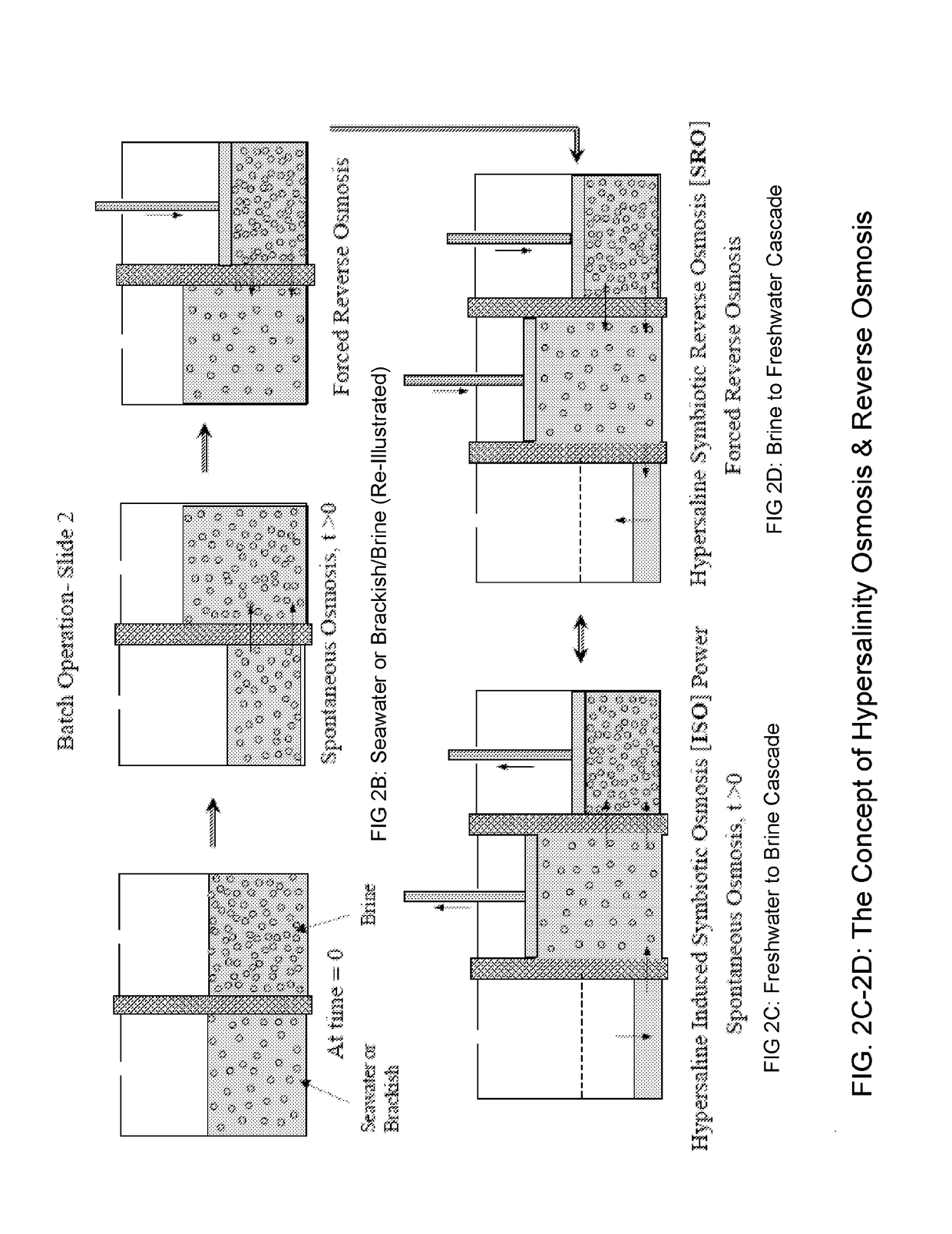
The inventor envisioned and patented a technology (U.S. Pat. No. 8,545,701) that employs a Symbiotic Salinity Concept (Induced Symbiotic Osmosis [ISO] for Salinity Power Generation), however, there is no polymeric membrane technology in practice today, or anticipated in the future, that is adequate for commercial desalination that can withstanding the pressure required for desalinating or generating osmotic power from 25% brines at 3000 psi.

Method used


Image

  • Symbiotic reverse osmosis for maximizing desalinated water recovery from saline waters and brines
  • Symbiotic reverse osmosis for maximizing desalinated water recovery from saline waters and brines
  • Symbiotic reverse osmosis for maximizing desalinated water recovery from saline waters and brines

Examples


Embodiment Construction

[0042]Illustrative embodiments of the preferred embodiment are described below. In the interest of clarity, not all features of an actual implementation are described in this specification. It will of course be appreciated that in the development of any such actual embodiment, numerous implementation-specific decisions must be made to achieve the developer's specific goals, such as compliance with system-related and business-related constraints, which will vary from one implementation to another. Moreover, it will be appreciated that such a development effort might be complex and time-consuming but would nevertheless be a routine undertaking for those of ordinary skill in the art having the benefit of this disclosure.

[0043]In the specification, reference may be made to the spatial relationships between various components and to the spatial orientation of various aspects of components as the devices are depicted in the attached drawings. However, as will be recognized by those skille...


PUM

PropertyMeasurementUnit
Reynolds numberaaaaaaaaaa
osmotic pressureaaaaaaaaaa

Abstract

The present application includes a symbiotic reverse osmosis train system for maximizing desalinated water recovery, meanwhile yielding high salinity brine suitable for osmotic power generation or commercial salt production. The trains comprise a series of cells operating in an interrelated sequential pattern within a salinity field. Each cell forms a closed hydraulic brine loop having pumping means, power recovery means and shared semipermeable membranes between adjacent cells. Used are a semipermeable Flat Sheet or Hollow Fiber Membrane in desalination and osmotic power generation of brackish, seawater and brines of 15% salinity or more. Charging each cell in the train of cells with a formulated brine having a specified ionizable inorganic salt concentration and type, without permitting mixing of the given brines among adjacent cells. Allowing the train to achieve water recovery exceeding 85% with concentrated rejected brine of 28-30% salt content.

Description

TECHNICAL FIELD[0001]The present application relates generally to a symbiotic reverse osmosis system using semipermeable flat sheet and hollow fiber membranes panels design.DESCRIPTION OF THE PRIOR ART[0002]In 1959, two researchers at UCLA, Sidney Loeb and Srinivasa Sourirajan succeeded in producing a functional synthetic RO membrane from cellulose acetate polymer and based on this development, the world's first commercial RO plant was built in Coalinga in 1965. Today, reverse osmosis and membrane filtration elements are used for multitude of water treatment processes and applications and many types of membranes are developed and in use worldwide. However, all of these applications are functionally still limited by seawater salinity of 3.5%[0003]This serious operational limitation has promoted the applicant of this invention to consider rather new approach that allows the use of the technology not only for seawater, but also for brines of different composition, solutes and salinity ...

Claims


Application Information

Patent Timeline
Patent Type & Authority Applications(United States)
IPC IPC(8): B01D61/06B01D63/08A23L27/40B01D65/02F03G7/00C02F1/44B01D63/04B01D61/02B01D61/04B01D61/08B01D61/12B01D61/58B01D61/00C02F103/08
CPCY02A20/131B01D2321/2083Y02W10/30C02F2303/20C02F2209/05C02F2209/02Y02W10/37B01D2321/04F03G7/005B01D65/02B01D61/08B01D61/04B01D61/022B01D61/002C02F2103/08A23V2002/00B01D61/06B01D61/12B01D61/58B01D63/04B01D63/082B01D2311/14B01D2311/246B01D2311/2642B01D2311/2673B01D2313/246C02F1/441C02F1/444C02F2303/10A23L27/40B01D61/025Y02A20/128Y02A20/124B01D61/026
Inventor KELADA, MAHER ISAAC
Owner KELADA MAHER ISAAC
Why Eureka
Try Eureka