High energy resolution / high x-ray flux photon counting detector

a detector and high energy resolution technology, applied in the field of photon counting detectors, can solve the problems of reducing image quality, reducing image quality, and the direct conversion of photon counting detector pixels is not well-suited for conventional non-spectral ct applications

Active Publication Date: 2018-07-12
KONINKLJIJKE PHILIPS NV
View PDF16 Cites 8 Cited by
  • Summary
  • Abstract
  • Description
  • Claims
  • Application Information

AI Technical Summary

Benefits of technology

[0007]In one aspect, an imaging system includes a detector module. The detector module includes a block of a plurality of direct conversion photon counting detector pixels and corresponding electronics with hardware for both high energy resolution imaging mode and high X-ray flux imaging mode connected with the block of the plurality of direct conversion photon counting detector pixels.
[0008]In another aspect, a method includes identifying a scanning mode for a selected imaging protocol, wherein the scanning modes includes one of a higher energy resolution mode and a higher X-ray flux mode, configuring a detector module, which is configurable for both the higher energy resolution mode and the higher X-ray

Problems solved by technology

When pulses overlap, their amplitudes combine so that the individual pulses may not be discernable from the combination, and the peak energy of a pulse is shifted by the amplitude contribution of the overlapping pulse such that the energy distribution of the detected photons may be erroneous, thereby reducing image quality.
In conventional non-spectral CT, the X-ray flux rate can be on the order of hundreds of Mcps per channel and thus d

Method used


Image

  • High energy resolution / high x-ray flux photon counting detector
  • High energy resolution / high x-ray flux photon counting detector
  • High energy resolution / high x-ray flux photon counting detector

Examples


Embodiment Construction

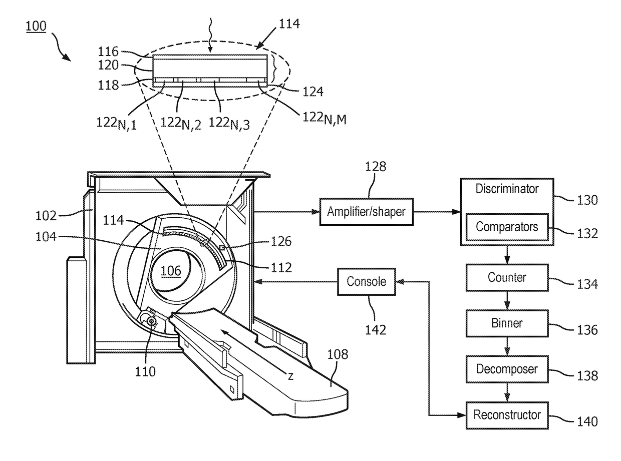
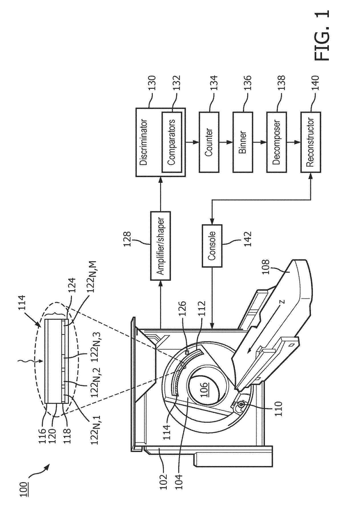
[0021]Initially referring to FIG. 1, an imaging system 100 such as a computed tomography (CT) scanner is schematically illustrated. The imaging system 100 includes a stationary gantry 102 and a rotating gantry 104, which is rotatably supported by the stationary gantry 102. The rotating gantry 104 rotates around an examination region 106 about a longitudinal or z-axis. A subject support 108, such as a couch, supports an object or subject in the examination region 106. The imaging system 100 includes a radiation source 110, such as an X-ray tube, which is supported by and rotates with the rotating gantry 104 around the examination region 106 about the longitudinal or z-axis 108. The radiation source 110 emits ionizing (x-ray) radiation that traverses the examination region 106 and a portion of a subject or an object located therein.

[0022]The imaging system 100 includes a detector array 112 that subtends an angular arc opposite the examination region 106 relative to the radiation sourc...


PUM


Abstract

An imaging system (100) includes a detector module (114). The detector module includes a block (300) of a plurality of direct conversion photon counting detector pixels (122) and corresponding electronics (124, 604, 606, 132, 134 or 124, 128, 130, 134, 802) with hardware for both high energy resolution imaging mode and high X-ray flux imaging mode connected with the block of the plurality of direct conversion photon counting detector pixels. A method includes identifying a scanning mode for a selected imaging protocol, wherein the scanning modes includes one of a higher energy resolution mode and a higher X-ray flux mode, configuring a detector module, which is configurable for both the higher energy resolution mode and the higher X-ray flux mode, based on the identified scanning mode, performing the scan with the detector module configured for the mode of the selected imaging protocol, and processing scan data from the scan, generating volumetric image data.

Description

FIELD OF THE INVENTION[0001]The following generally relates to a photon counting detector and more particularly to a photon counter detector that is configured for both high energy (spectral) resolution and high x-ray flux imaging examinations, and is described with particular application to computed tomography (CT); however, the following is also amenable to other imaging modalities.BACKGROUND OF THE INVENTION[0002]A computed tomography (CT) scanner includes a rotating gantry rotatably mounted to a stationary gantry. The rotating gantry supports an X-ray tube. A detector array is located opposite the X-ray tube, across an examination region. The rotating gantry and the X-ray tube rotate around the examination region about a longitudinal or z-axis. The X-ray tube is configured to emit poly-energetic ionizing radiation that traverses the examination region and illuminates the detector array. The detector array includes a one or two dimensional array of detector pixels that detect the...

Claims


Application Information

Patent Timeline
IPC IPC(8): G01T1/24
CPCG01T1/247G01T1/243G01T7/00
Inventor BLEVIS, IRA MICAHSTEADMAN BOOKER, ROGERHERRMANN, CHRISTOPH
Owner KONINKLJIJKE PHILIPS NV
Why Eureka
Try Eureka