
Hybrid vehicle

a hybrid vehicle and hybrid technology, applied in the direction of engine-driven generators, transportation and packaging, etc., can solve the problems of increasing the rotation speed of the engine, the inability to secure sufficient braking torque, and the limited value of chargeable electric power, so as to suppress the excessive deceleration of the hybrid vehicle, improve energy efficiency, and suppress the effect of rapid increase in engine rotation speed

Active Publication Date: 2018-07-26
TOYOTA JIDOSHA KK
View PDF0 Cites 5 Cited by
  • Summary
  • Abstract
  • Description
  • Claims
  • Application Information

AI Technical Summary

Benefits of technology

This patent relates to a hybrid vehicle that has a limited amount of battery power. The patent describes a method to conserve power and reduce the likelihood of excessive engine speed when the vehicle is being controlled to cruise. This is accomplished by using a first rotating electric machine to increase the speed of the engine and applying the engine's brakes to slow down the vehicle. This technique not only helps to decrease the need for regenerative braking but also reduces the amount of charging needed for the battery. Overall, this patent provides a way for a hybrid vehicle to use its limited battery power more efficiently and operate more efficiently in cruise control modes.

Problems solved by technology

As a result, there is a possibility that chargeable electric power is limited to a value smaller than a threshold.
When this happens, in the second rotating electric machine, it is not possible to secure sufficient braking torque.
However, when this happens, the rotation speed of the engine increases even during traveling on a relatively long downhill, and there is a possibility that a sense of discomfort is given to a user.
In a case where the simulated stepped gear shift control is executed even though the deceleration torque is not temporally stable (for example, repeatedly increases and decreases) during the execution of the cruise control, the gear ratio is changed needlessly, whereby there is a possibility that vibration, noise, or the like occurs in the hybrid vehicle and comfortableness of the user is deteriorated.
In a case where the engine brake torque is greater than the deceleration torque, the hybrid vehicle is decelerated excessively, and cruise traveling cannot be continued.

Method used


Image

  • Hybrid vehicle
  • Hybrid vehicle
  • Hybrid vehicle

Examples


embodiment

[0030]Overall Configuration of Hybrid Vehicle

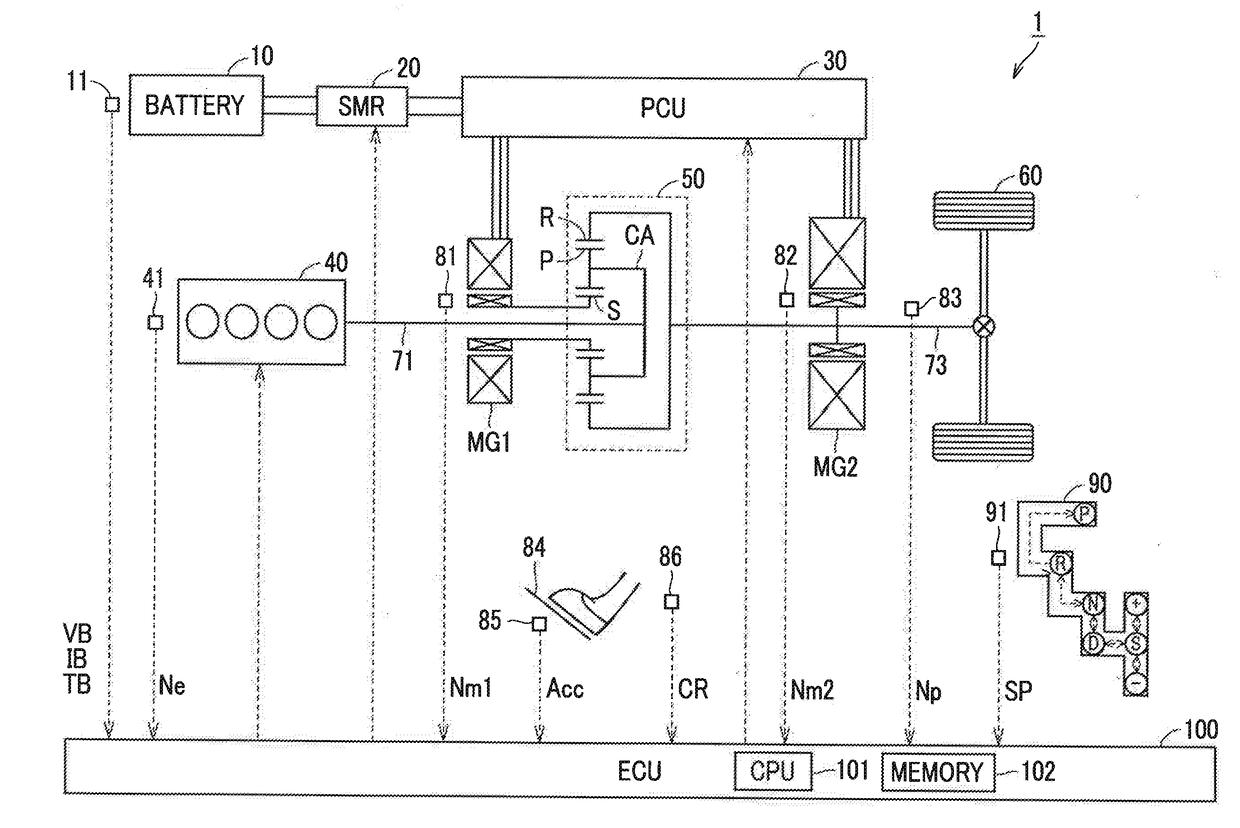
[0031]FIG. 1 is a diagram schematically showing the overall configuration of a hybrid vehicle according to the embodiment. Referring to FIG. 1, a vehicle 1 includes a battery 10, a system main relay (SMR) 20, a power control unit (PCU) 30, an engine 40, a motor generator (MG) MG1, a planetary gear mechanism 50, a motor generator MG2, and an electronic control unit (ECU) 100.

[0032]The battery 10 is a rechargeable electric power storage device. The battery 10 includes a secondary battery represented by a nickel-hydrogen battery or a lithium-ion battery. Instead of the battery 10, a capacitor, such as an electric double layer capacitor, may be used. Hereinafter, a charging direction to the battery 10 will be described as a positive direction of a current (electric power).

[0033]The battery 10 is provided with a battery sensor 11. The battery sensor 11 includes a voltage sensor, a current sensor, and a temperature sensor (all of these are not ...


PUM


Abstract

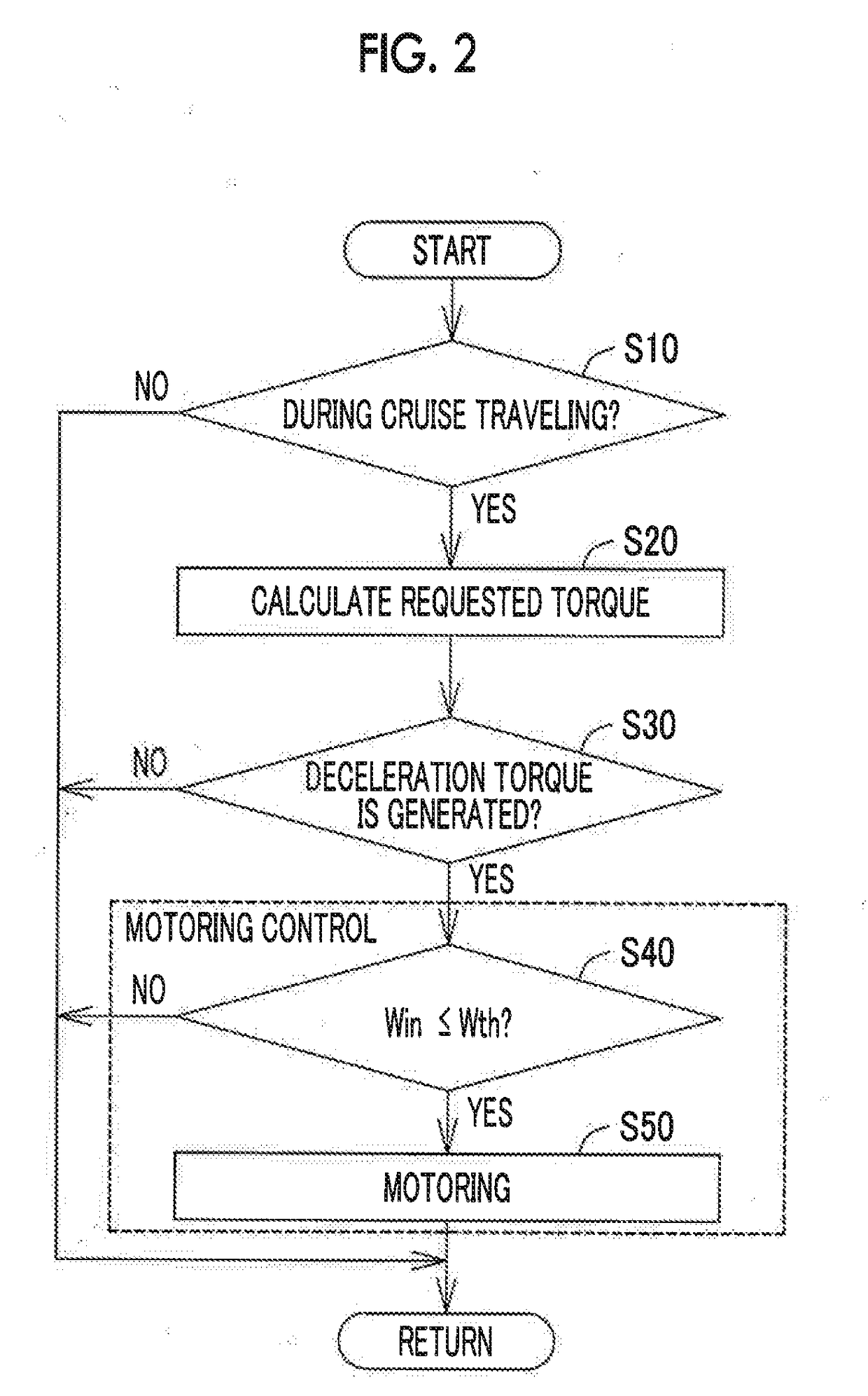
A hybrid vehicle includes an engine, a first rotating electric machine, a second rotating electric machine coupled to drive wheels of the hybrid vehicle, a planetary gear mechanism configured to mechanically couple the engine, the first rotating electric machine, and the second rotating electric machine, an electric power storage device configured to perform charging and discharging with the first rotating electric machine and second rotating electric machine, and an electronic control unit configured to, in a case where cruise control is requested or in a case where deceleration torque is requested by the cruise control, execute motoring control and simulated stepped gear shift control.

Description

INCORPORATION BY REFERENCE[0001]The disclosure of Japanese Patent Application No. 2017-009172 filed, on Jan. 23, 2017 including the specification, drawings and abstract is incorporated herein by reference in its entirety.BACKGROUND1. Technical Field[0002]The present disclosure relates to a hybrid vehicle, and more specifically, to control of a hybrid vehicle that travels while executing cruise control that is control for maintaining a vehicle speed at a target value.2. Description of Related Art[0003]A hybrid vehicle including an engine, first and second rotating electric machines, a planetary gear mechanism, and a battery is known (for example, see Japanese Unexamined Patent Application Publication No. 2007-001392 (JP 2007-001392 A)). The second rotating electric machine is coupled to drive wheels of the hybrid vehicle. The planetary gear mechanism mechanically couples the engine, the first rotating electric machine, and the second rotating electric machine. The battery performs ch...

Claims


Application Information

Patent Timeline
IPC IPC(8): B60L15/20B60K6/442B60K6/547B60L7/16B60L7/24B60L11/14B60W10/08B60W10/115B60W20/30B60W10/184F16H61/08F16H61/686B60L50/16
CPCB60L15/2009B60K6/442B60K6/547B60L7/16B60L7/24B60L11/14B60W10/08B60W10/115B60W20/30B60W10/184F16H61/08F16H61/686F16H59/42F16H61/16F16H63/50F16H3/728F16H2061/6603B60W2510/105B60W10/06B60W10/11B60W10/26B60W30/143B60W30/19B60W2710/0644B60W2710/0666B60W2710/083B60K6/445B60L15/2054B60W30/18127B60W30/18136B60W2030/18081B60W2510/0657B60W2510/083B60L50/16F16H59/18F16H59/44F16H59/68F16H2059/366F16H2061/6615Y02T10/62Y02T10/64Y02T10/7072Y02T10/72
Inventor KATO, SHUNYASUGAI, MASAYA
Owner TOYOTA JIDOSHA KK
Learn More