
Water treatment method and water treatment apparatus

a water treatment method and water treatment apparatus technology, applied in the direction of membranes, sustainable biological treatment, biological water/sewage treatment, etc., can solve the problems of unstable treatment, difficult long-term stable filtration, and membrane falling into a state of difficult filtration, so as to achieve long-term stable filtration and short contact time

Inactive Publication Date: 2018-08-09
MITSUBISHI ELECTRIC CORP
View PDF0 Cites 4 Cited by
  • Summary
  • Abstract
  • Description
  • Claims
  • Application Information

AI Technical Summary

Benefits of technology

The present invention is a water treatment method and apparatus that uses a hydrophobic membrane to filter and purify water. This method has two main steps: a filtration step and an ozone injection step. An ozone injection amount index, which is the amount of ozone injected during the ozone injection step divided by the operation time of the filtration step, is calculated every cycle. This index is used to set the ozone injection amount for the next cycle. This method allows for long-term stable filtration without special pretreatment or facilities, making it more efficient than other methods.

Problems solved by technology

However, those technologies have problems in that treatment is unstable because of being strongly affected by the properties of the water to be treated or flocculated matter, a water temperature, water flow, and the like, and an extensive sedimentation tank or floatation separation tank is required.
However, there has been a problem in that pollutants are accumulated onto the surface of the membrane along with filtration and thus the pores are blocked, and the membrane falls into a state of being difficult to perform filtration.
In particular, a hydrophobic organic membrane has a high affinity for a hydrophobic pollutant to be contained in the water to be treated, and blocking is liable to occur, with the result that it is difficult to perform long-term stable filtration.

Method used


Image

  • Water treatment method and water treatment apparatus
  • Water treatment method and water treatment apparatus
  • Water treatment method and water treatment apparatus

Examples


first embodiment

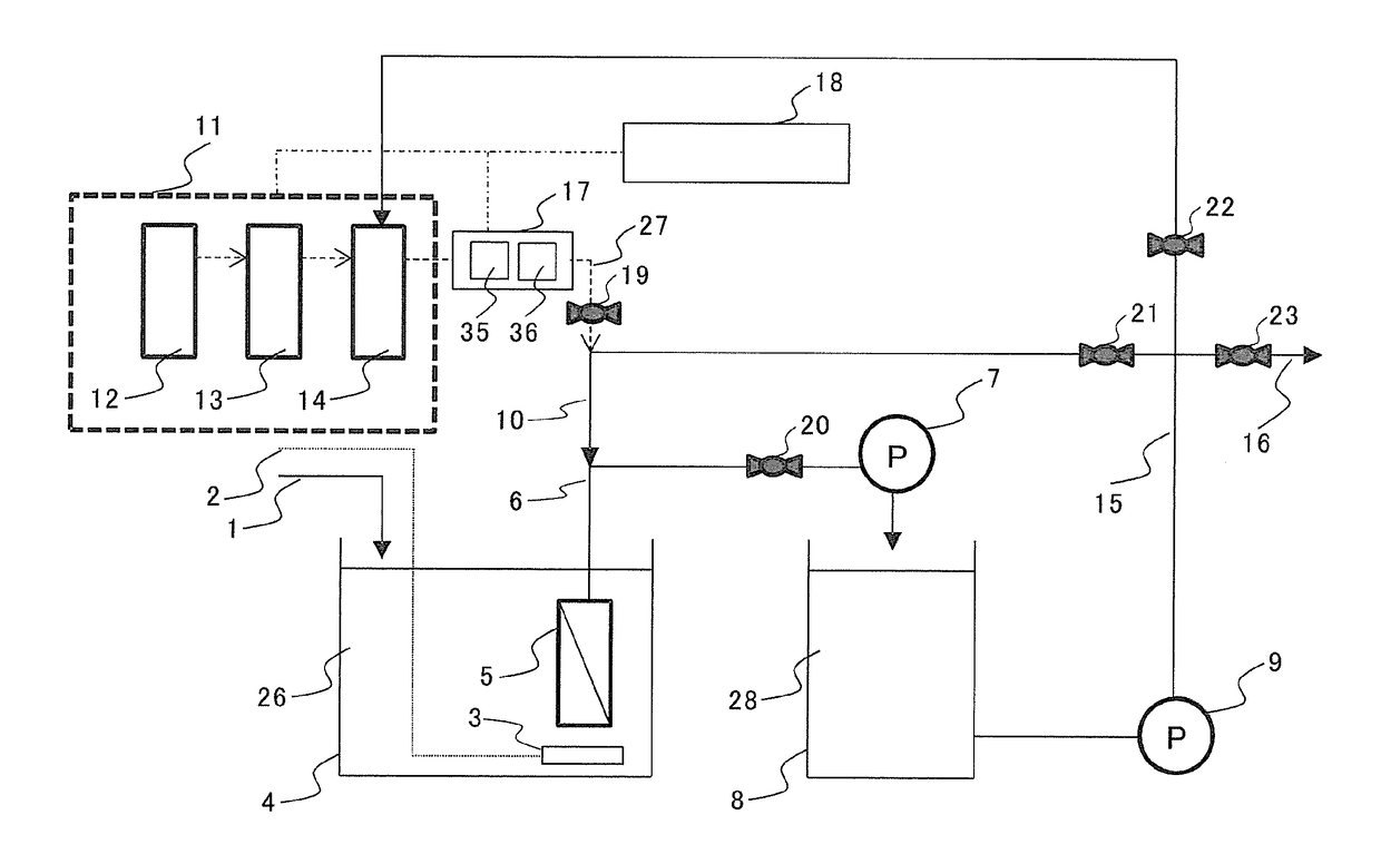
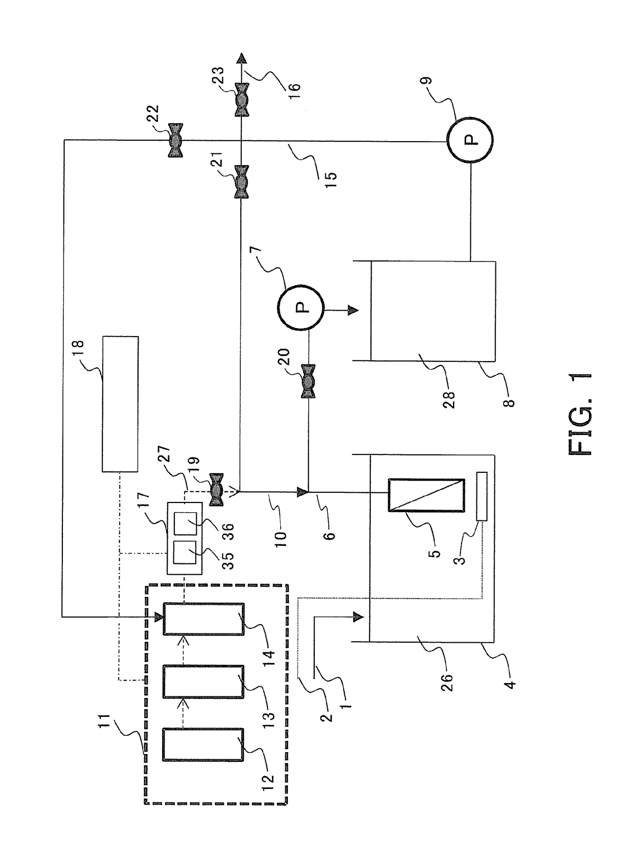
[0029]FIG. 1 is a view for illustrating an entire water treatment system in the case of applying a water treatment apparatus according to a first embodiment of the present invention to an immersed membrane bioreactor. The water treatment apparatus of FIG. 1 includes: an introduction pipe 1 for water to be treated for introducing water to be treated into a biological treatment tank 4; an air introduction pipe 2 for blowing air into the biological treatment tank 4. The air introduction pipe 2 is connected to an air diffuser 3.

[0030]In the biological treatment tank 4, activated sludge 26 is retained, and in addition, a separation membrane 5 is arranged so as to be immersed in the activated sludge 26. A permeate water transfer pipe 6 is connected to the separation membrane 5. Further, a valve 20 and a membrane filtration pump 7 are mounted to the permeate water transfer pipe 6.

[0031]In addition, a treated water transfer pipe 15 is connected to a treated water tank 8 through a pump 9. Mo...

second embodiment

[0113]In a second embodiment of the present invention, description is given of a water treatment apparatus capable of reducing the usage amount of ozone by eliminating unnecessary washing with ozone.

[0114]FIG. 5 is a view for illustrating an entire water treatment system in the case of applying a water treatment apparatus according to the second embodiment of the present invention to an immersed membrane bioreactor. When the configuration of FIG. 5 of the second embodiment is compared to the configuration of FIG. 1 of the preceding first embodiment, the configuration of FIG. 5 differs from the configuration of FIG. 1 in that the membrane property detector 24 and the transmembrane pressure difference detector 25 are further mounted to the permeate water transfer pipe 6. In view of the foregoing, the description is given with a focus on those differences.

[0115]As specifically described in the preceding first embodiment, the present invention enables long-term stable filtration by brin...

specific examples

[0150]For the water treatment apparatus illustrated in FIG. 2, the effects of the present invention were examined by way of Examples based on specific data. A pressure gauge was used as the transmembrane pressure difference detector 25 without using the membrane property detector 24. A hollow fiber membrane module using a microfiltration membrane made of PVDF was used as a membrane. Under each of the conditions, a cumulative operation time of the filtration step was unified to 1,800 minutes.

[0151]Urban sewage water was used as water to be treated, and was treated through use of activated sludge. Water in an amount required in a testing period was sampled at once, and was stirred to be homogenized in a tank separately prepared. In addition, four separation membranes 5 were simultaneously immersed in the biological treatment tank 4. Thus, experiments of Example 1, Example 2, Example 3, and Comparative Example 1 described below were each performed. That is, for all the separation membr...


PUM


Abstract

Provided is a water treatment method, in which a cycle including: a filtration step of filtering water to be treated through a separation membrane from a primary side to a secondary side of the separation membrane; and a backwashing step of washing the separation membrane from the secondary side to the primary side is repeated, the water treatment method including the steps of: injecting, into the separation membrane, ozone to be used in the backwashing step; and when, of the repeated cycles, a previous cycle is defined as a first cycle and a following cycle subsequent to the first cycle is defined as a second cycle, setting an ozone injection amount to be injected in the second cycle to a value equal to or less than an ozone injection amount injected in the first cycle.

Description

TECHNICAL FIELD[0001]The present invention relates to a water treatment technology using a membrane, and more specifically, to a water treatment method and water treatment apparatus including washing treatment for modification of a hydrophobic membrane.BACKGROUND ART[0002]A solid-liquid separation technology involving separating, from water to be treated, pollutants contained in the water to be treated to obtain clean treated water is widely used in water treatment, such as water purification or sewage water treatment.[0003]Examples of the solid-liquid separation technology include: a flocculation technology involving flocculating pollutants contained in water to be treated through addition of a flocculant, to thereby separate the pollutants by gravity sedimentation; and a dissolved air floatation technology involving injecting microbubbles into water to be treated containing flocculated matter to cause the microbubbles to adsorb the flocculated matter thereonto, to thereby separate...

Claims


Application Information

Patent Timeline
IPC IPC(8): B01D65/02C02F1/44C02F3/12C02F1/00B01D69/02
CPCB01D65/02C02F1/44C02F3/1273C02F1/008B01D69/02B01D2321/04B01D2321/168C02F2303/16C02F2209/03C02F2209/23B01D2325/38Y02W10/10
Inventor IMAMURA, EIJIYAMAUCHI, TOKIKOYASUNAGA, NOZOMU
Owner MITSUBISHI ELECTRIC CORP
Learn More