Optical laminate, method of producing optical laminate, optical element, and image display

a technology of optical laminates and optical elements, applied in the field of optical laminates, can solve the problems of time and trouble in production, and achieve the effects of superior film strength, easy peeling, and superior film strength

Active Publication Date: 2018-08-09
NITTO DENKO CORP
View PDF1 Cites 9 Cited by
  • Summary
  • Abstract
  • Description
  • Claims
  • Application Information

AI Technical Summary

Benefits of technology

[0014]The optical laminate of the present invention achieves a superior film strength and a property that a void-provided layer and a pressure-sensitive adhesive / adhesive layer are not easily peeled from each other. The production method of an optical laminate of the present invention can produce an optical laminate of the present invention that achieves superior film strength and a property that a void-provided layer and a pressure-sensitive adhesive / adhesive layer are not easily peeled from each other. The optical laminate of the present invention may be, for example, an optical laminate (hereinafter, also referred to as a “laminated film of the present invention”) further including a resin film, wherein the void-provided layer, the intermediate layer, and the pressure-sensitive adhesive / adhesive layer are stacked on the resin film in this order. The present invention, however, is not limited thereto. The optical laminate of the present invention may be used for an optical element and an image display of the present invention, for example. The present invention, however, is not limited thereto and can be used for any purpose.

Problems solved by technology

Forming air layers in such a manner, however, requires disposing the components at regular spacings, which prevents the components from being stacked sequentially and causes time and trouble in production.

Method used


Image

  • Optical laminate, method of producing optical laminate, optical element, and image display
  • Optical laminate, method of producing optical laminate, optical element, and image display
  • Optical laminate, method of producing optical laminate, optical element, and image display

Examples


example 1

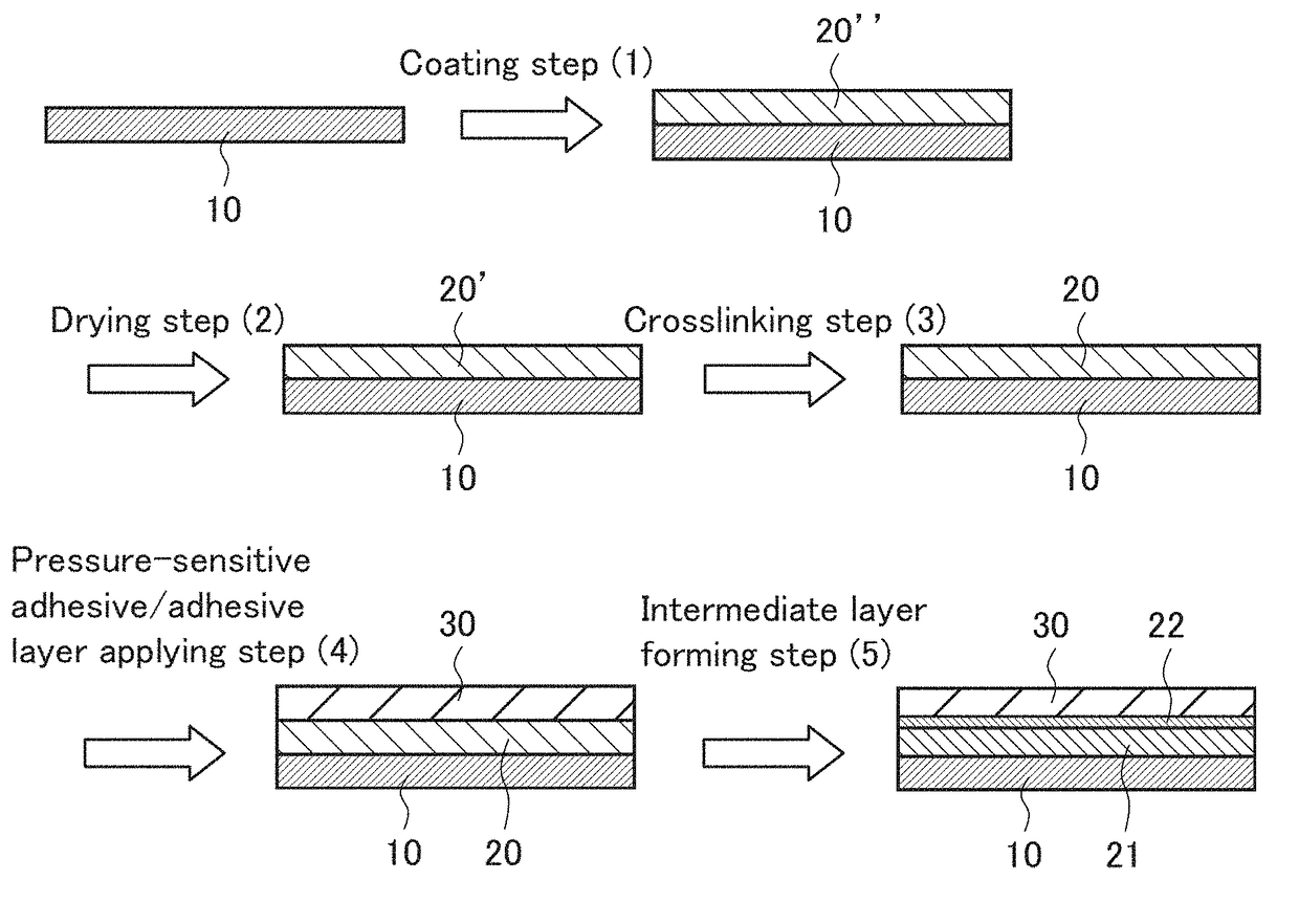
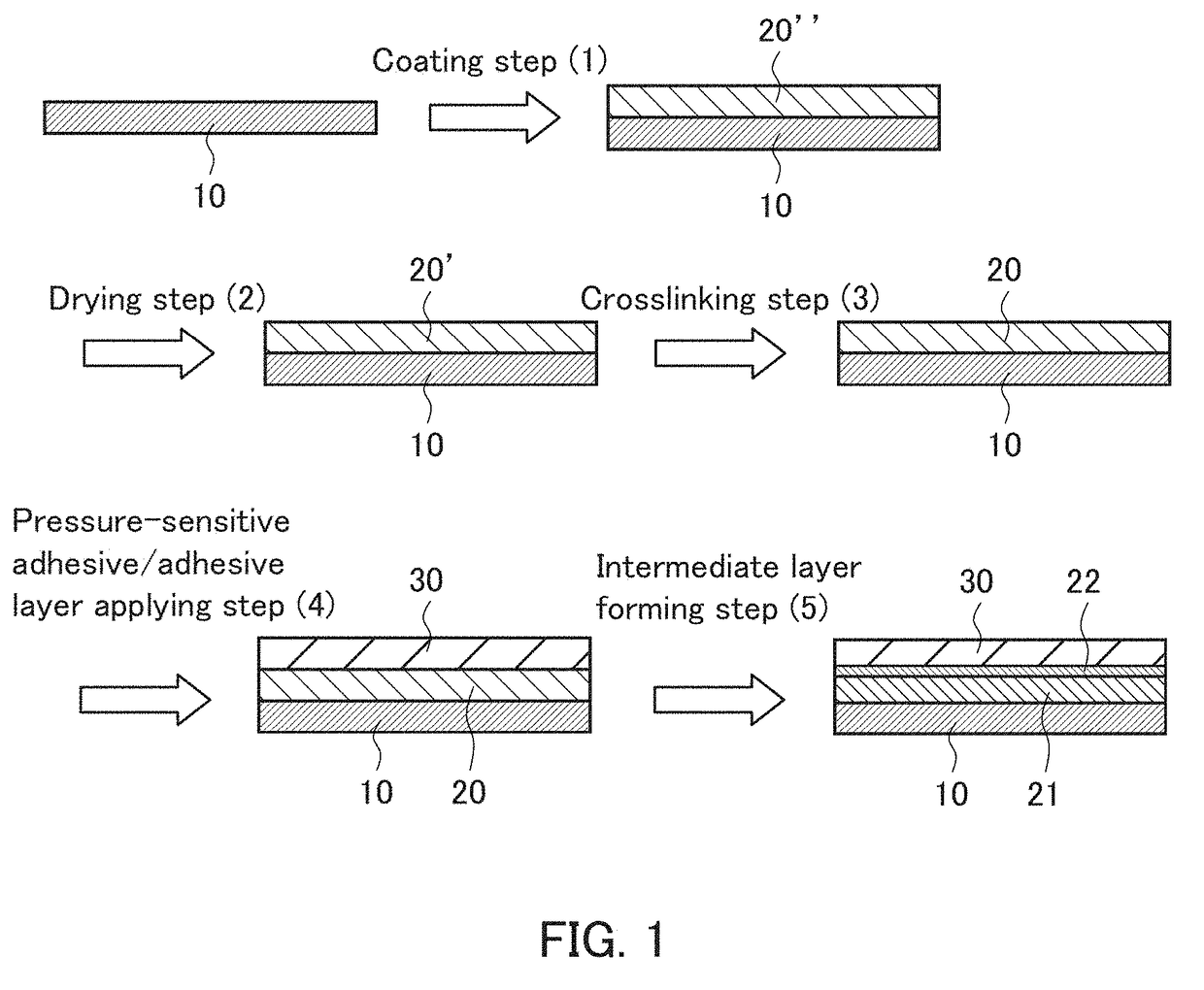
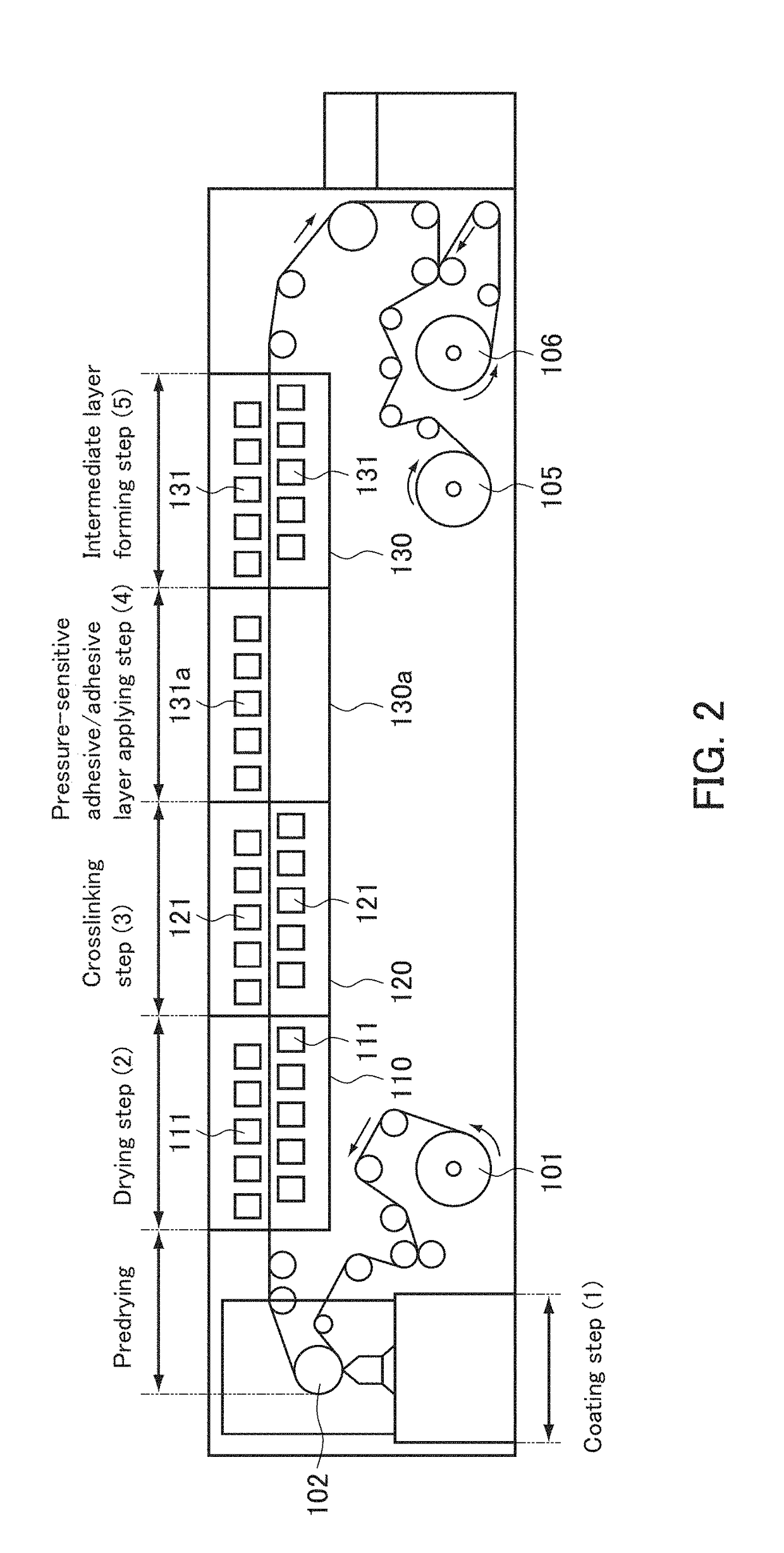
[0184]In the present example, a laminated film of the present invention (laminated film roll) was produced as described below.

[0185](1) Gelation of Silicon Compound

[0186]0.95 g of MTMS which is the precursor of a silicon compound was dissolved in 2.2 g of DMSO. 0.5 g of 0.01 mol / L oxalic acid aqueous solution was added to the mixture, and the resultant was stirred at room temperature for 30 minutes to hydrolyze MTMS, thereby preparing tris(hydroxy) methylsilane.

[0187]0.38 g of ammonia water having a concentration of 28% and 0.2 g of pure water were added to 5.5 g of DMSO, then the aforementioned mixture that had been subjected to the hydrolysis treatment was added thereto, and the resultant was stirred at room temperature for 15 minutes to gelate tris(hydroxy)methylsilane, thereby obtaining a gelled silicon compound.

[0188](2) Aging Treatment

[0189]The aging treatment was carried out as follows. The mixture that had been subjected to the gelation treatment was incubated at 40° C. for ...

example 2

[0197]A laminated film roll was produced in the same manner as in Example 1 except that 0.018 g of 5 wt % 1,2-bis(trimethoxysilyl) ethane was added to 0.75 g of the sol liquid after addition of the photobase generator solution to adjust the coating liquid in the “(3) Pulverizing treatment and addition of photobase generator” step of Example 1.

example 3

[0198]A laminated film roll was produced in the same manner as in Example 1 except that the amount of the photobase generator added to 0.75 g of the sol liquid was 0.054 g in the “(3) Pulverizing treatment and addition of photobase generator” step of Example 1.


PUM

PropertyMeasurementUnit
refractive indexaaaaaaaaaa
thicknessaaaaaaaaaa

Abstract

The present invention is intended to provide an optical laminate that achieves a superior film strength and a property that a void-provided layer and a pressure-sensitive adhesive / adhesive layer are not easily peeled from each other. The optical laminate of the present invention includes: a void-provided layer; an intermediate layer; and a pressure-sensitive adhesive / adhesive layer, wherein the void-provided layer, the intermediate layer, and the pressure-sensitive adhesive / adhesive layer are stacked in this order, and the intermediate layer is formed by forming the pressure-sensitive adhesive / adhesive layer on the void-provided layer.

Description

TECHNICAL FIELD[0001]The present invention relates to an optical laminate, a method of producing an optical laminate, an optical element, an image display, a method of producing an optical element, and a method of producing an image display.BACKGROUND ART[0002]Disposing two substrates at a regular spacing forms an air layer which is a void space between the substrates. The air layer formed between the substrates serves as a low refractive layer that reflects light entirely, for example. Thus, for example, in the case of an optical film, components such as a prism, a polarizing film, and a polarizing plate are disposed at regular spacings to provide air layers each of which serves as a low refractive index layer between the components. Forming air layers in such a manner, however, requires disposing the components at regular spacings, which prevents the components from being stacked sequentially and causes time and trouble in production. Combining optical elements thorough a spacer (...

Claims


Application Information

Patent Timeline
Patent Type & Authority Applications(United States)
IPC IPC(8): G02B1/14C09J7/29B32B27/06B32B7/02G02B1/12
CPCG02B1/14C09J7/29B32B27/06B32B7/02G02B1/12B32B2305/026B32B5/18B32B27/00C09J2203/318C09J2400/243C09J2301/302C09J7/20B32B3/26B32B7/10B32B27/36B32B2038/0076B32B2457/20B32B2307/40G06F3/00
Inventor HATTORI, DAISUKEHARUTA, HIROMOTONAKAMURA, KOZOTAKEMOTO, HIROYUKI
Owner NITTO DENKO CORP
Why Eureka
Try Eureka