Device Which Applies Work To Outside With Environmental Thermal Energy

a technology of thermal energy and a device, applied in the field of power machinery, can solve the problems of high cost, danger, exhaust, pollution and damage to the environment, limited power generation with clean energy, hydropower, wind power and terrestrial heat,

Inactive Publication Date: 2018-08-16
YU YIGANG
View PDF7 Cites 0 Cited by
  • Summary
  • Abstract
  • Description
  • Claims
  • Application Information

AI Technical Summary

Problems solved by technology

However, all technologies for obtaining energy have their own shortcomings, such as high cost, danger, exhaust, pollution and damage to the environment.
Even power generation with clean energy, such as hydropower, wind power and terrestrial heat, is limited by the geographic...

Method used


Image

  • Device Which Applies Work To Outside With Environmental Thermal Energy
  • Device Which Applies Work To Outside With Environmental Thermal Energy
  • Device Which Applies Work To Outside With Environmental Thermal Energy

Examples


embodiment 1

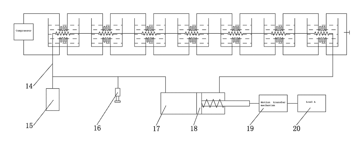
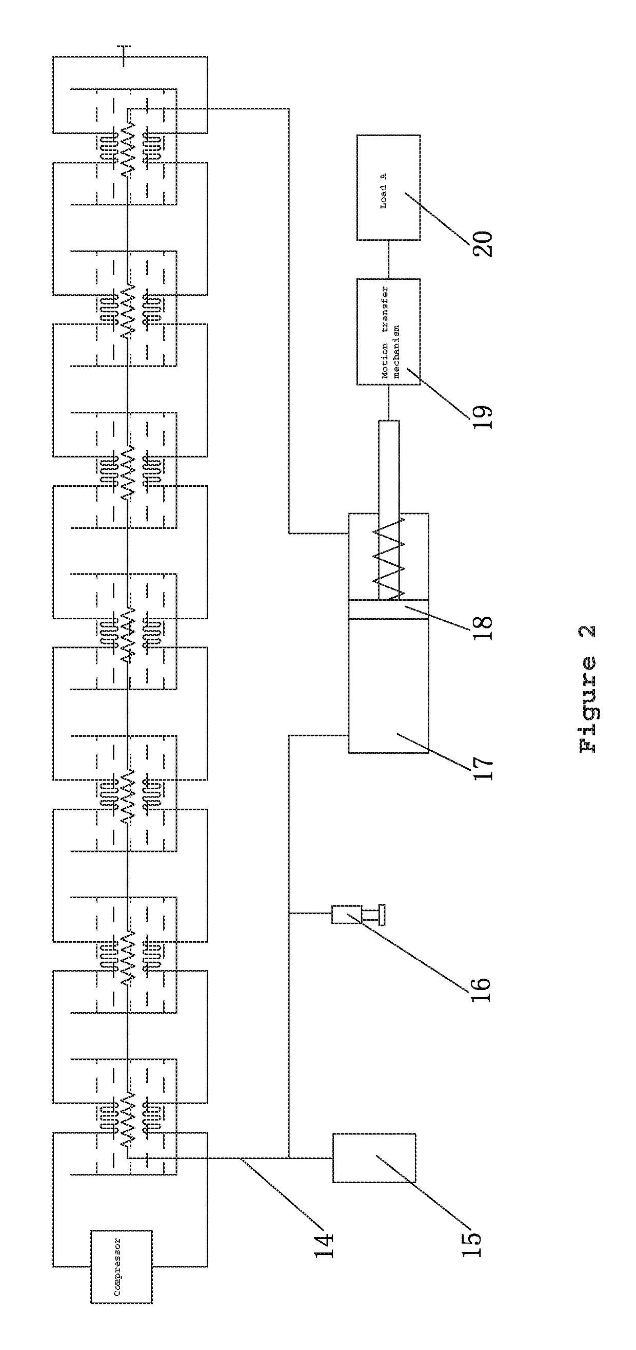
[0028]See FIG. 2. Its working process is as follows:

[0029]In the heat pump part, the Embodiment omits the energy recovery part, its working principle is shown in the part of the positive feedback heat pump.

[0030]Take some liquid with high expansion as the working medium, the pipeline (14), a Hydraulic cylinder(17), a Starter (15) and other accessories are interconnected. When the starter is heated (the starter can be placed in the container with the highest temperature, hot water can be added into the container with the highest temperature at the beginning), the working medium expands, so that the intensity of pressure inside the entire connector increases. Here, the Hydraulic cylinder (17) is connected into a differential mode, at first the Piston (18) moves to the right, at the same time, the Piston (18) moves the working medium to the right of the Piston (18) and in the pipeline passes through a multistage heat exchange device towards the left of the piston, the temperature of wa...

embodiment 2

[0032]The working process of the heat pump part is the same as embodiment 1.

[0033]In the drawing, the left end of the multistage heat exchange container has the highest temperature, and the right end has the lowest temperature. The working process is as follow, when the Liquid moving cylinder (22) rotates to a certain angle clockwise, under the action of gravity a Heavy piston (23) moves downward, at the same time, it presses the liquid working medium, and the liquid working medium passes through the multistage heat exchange device, and moves to the left of Liquid moving cylinder (22), when passing through the multistage heat exchange device, the working medium gradually heats up and expands, which results in increase of the volume in the whole connecting vessels, the piston of the Hydraulic cylinder (24) is pushed to apply work to the outside through the Motion transfer mechanism (25), compress the return spring at the same time, and drives the flywheel to rotate, applies work on L...

embodiment 3

[0035]The working process of the heat pump part is the same as embodiment 1.

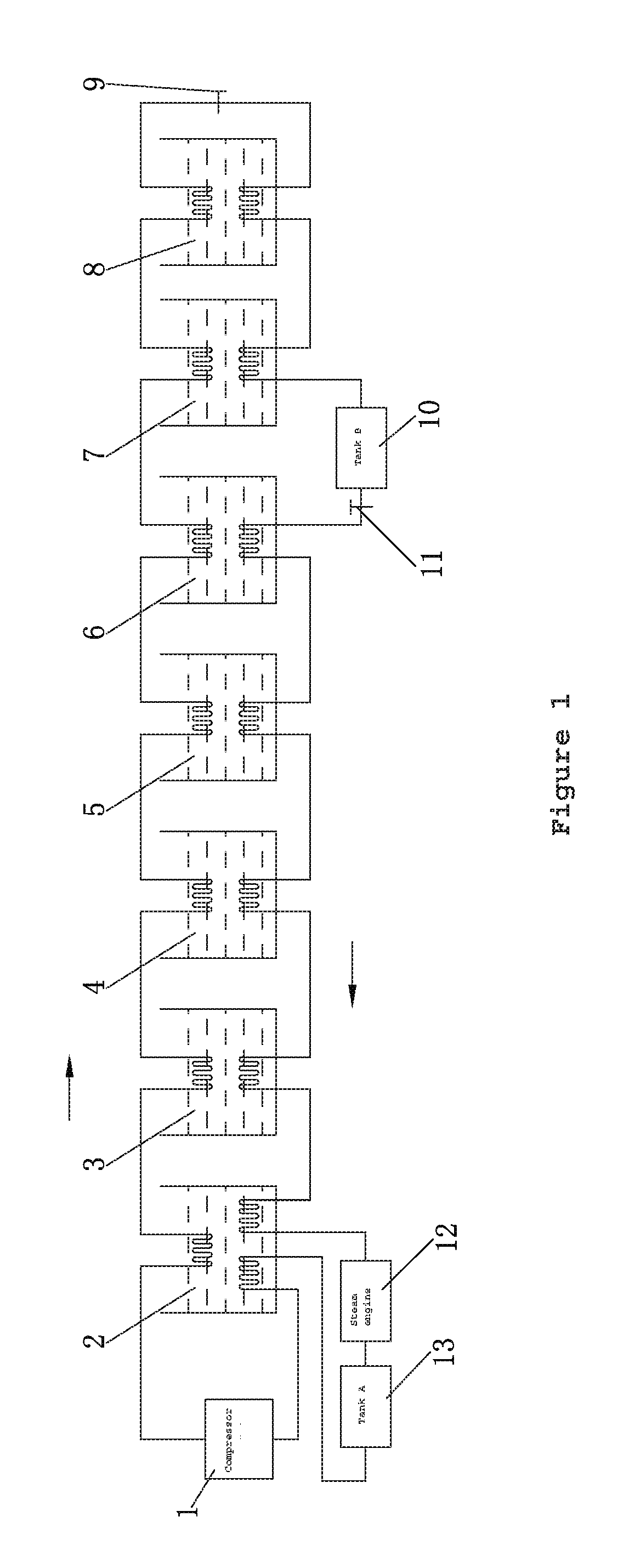
[0036]This method applies work with low-temperature steam, it is relatively suitable for power plants. In the drawing the temperature of water in the multistage heat exchange container is the highest on the left and lowest on the right. The working medium with a low boiling point is placed in a Liquid storage tank (30). At the start, the working Medium pump (29) is started and delivers the liquid working medium through a One-way valve (28) and a multistage heat exchange container to Steam Tank A (27). During the process, the working medium is gradually heated and gasified, and after it is heated in the container with the highest temperature the gaseous working medium it then goes through a Valve (34) and drives the Steam engine (33) (or turbine motor, etc.) to apply work on Load C (32). After working, the steam goes into Steam Tank B(31), and then passes through the containers for multistage cooling and liqu...


PUM


Abstract

The present invention relates to a device which applies work to the outside with environmental thermal energy, including a positive feedback heat pump system and a reciprocating multi-stage heat exchange working system. A high temperature heat source and a low temperature heat source are produced using a positive feedback heat pump, and at the same time the reciprocating multistage heat exchange working device applies work with heat energy and cold energy. As we can get several times of heat energy and cold energy when a certain amount of electric energy is consumed by a heat pump, and the thermal efficiency of the reciprocating multistage heat exchange working system is 100% theoretically, so we can get several times of electric energy. That is to say, its output is much bigger than its input, and the device can run without electric energy input, and provide electric energy to the outside.

Description

FIELD OF THE INVENTION[0001]The present invention relates to the power machinery technical field, and more specifically to a device for applying work to the outside by using environmental thermal energy.BACKGROUND OF THE INVENTION[0002]Because of constant economic development, each country has a huge requirement for energy that increases gradually. While the energy, such as oil, coal and natural gas, will be exhausted eventually, new energy has to be found for the continuous development of the economy. However, all technologies for obtaining energy have their own shortcomings, such as high cost, danger, exhaust, pollution and damage to the environment. Even power generation with clean energy, such as hydropower, wind power and terrestrial heat, is limited by the geographical environment, and a multitude of devices are required. The cost is extremely high, and it cannot resolve the increasingly urgent energy problem completely.[0003]There exists an abundance of energy in our living e...

Claims


Application Information

Patent Timeline
IPC IPC(8): F03C1/007F03C1/00F01B17/04
CPCF03C1/0073F03C1/002F01B17/04F01K27/00F25B30/02F03G7/04F25B40/00F25B2339/047F24D11/02
Inventor YU, YIGANG
Owner YU YIGANG
Why Eureka
Try Eureka