Method and apparatus for detecting cell reprogramming
a cell reprogramming and cell technology, applied in the field of identifying cell reprogramming process, can solve the problems of low efficiency of ips cell induction, burdensome task of identifying and tracing cells undergoing reprogramming, and inability to obtain a detailed “route map” from differentiated cells to ips cells
- Summary
- Abstract
- Description
- Claims
- Application Information
AI Technical Summary
Benefits of technology
Problems solved by technology
Method used
Image


Examples
example 2
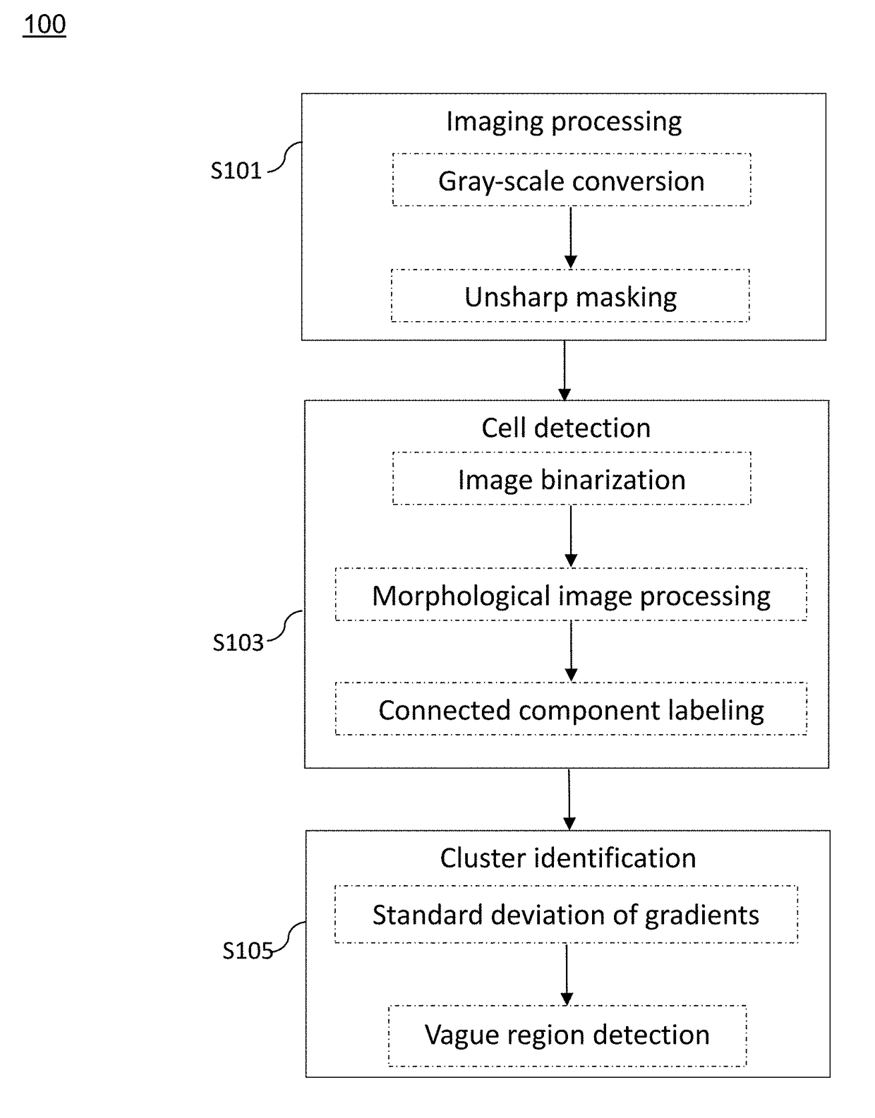
[0081]In this example, two successive fluorescent images were processed by the imaging processing step S101, the cell detection step S103, and the cluster identification step S105, as described above, and the results were shown in FIG. 4, in which panels (a) and (b) show the original image and the corresponding bright field contrast image, respectively, and panels (c) and (d) show the result after the steps S101 to S103 of the image of panel (a) but with different standard deviations of gradients.
[0082]As could be seen in panels (c) and (d) of FIG. 4, a vague (or smooth) region is found at the location(s) where the formation of iPS cells is taking place. The vagueness or smoothness is resulted from the stacking of the fluorescent cells during the reprogramming process. This result indicates the present method is capable of automatically identifying when and where the reprogramming process takes place from the fluorescence microscopic images.
[0083]These reprogrammed cell clusters can...
embodiment 2
[0090]In this embodiment, an exemplary implementation of the system of Embodiment 1 is described.
[0091]FIG. 5 shows a block diagram of the system for identifying cells undergoing reprogramming and reprogrammed cells from a fluorescence microscopic image of one or more cells which is explained in the first embodiment.
[0092]According to FIG. 5, the system 1000 comprises a processor 1100, a memory 1200, an image capturing apparatus 1300 and a storage medium 1400. As shown in FIG. 5, the processor 1100, the memory 1200, the image capturing apparatus 1300 and the storage medium 1400 are interconnected with one another via a system bus.
[0093]The image capturing apparatus 1300 corresponds to the fluorescent image-capturing apparatus of the first embodiment.
[0094]According to FIG. 5, the processor 1100 comprises an image processing section 101, a cell detection section 103 and a cluster identification section 105. The image processing section 101 performs the step S101 of the first embodime...
embodiment 3
[0098]The third aspect of the present disclosure is directed to a method and an apparatus for iPS detection by deep learning. The present embodiment 3 comprises the method, system and apparatus which are already explained in the embodiments 1 and 2 as well as the method and apparatus explained below.
[0099]According to certain embodiments of the present disclosure, the method and the apparatus for iPS detection by deep learning of the present embodiment deal with the following 6 types of classes (Classification 1 to 6). The classes are defined by cell distribution and image texture (especially, Classification 4 to 6).[0100]Class 1: Region with no cells[0101]Class 2: Region with separate cells[0102]Class 3: Region with clustering cells[0103]Class 4: Region with clustered cells[0104]Class 5: Region with tightly clustered cells[0105]Class 6: Region with iPS cells
[0106]FIG. 6 shows representative images for each of the above class. Specifically, for class 1, there are no cells in the fie...
PUM
| Property | Measurement | Unit |
|---|---|---|
| fluorescence microscopic image | aaaaa | aaaaa |
| fluorescence microscopic | aaaaa | aaaaa |
| size | aaaaa | aaaaa |
Abstract
Description
Claims
Application Information
PatSnap Eureka turns technology decisions into work you can execute. Powered by our Innovation Knowledge Graph, it runs expert workflows across engineering, life sciences, materials and intellectual property. Get your review-ready output in minutes.


