
Photothermal imaging device and system

Active Publication Date: 2018-08-30
UNIV OF NOTRE DAME DU LAC
View PDF2 Cites 22 Cited by
  • Summary
  • Abstract
  • Description
  • Claims
  • Application Information

AI Technical Summary

Benefits of technology

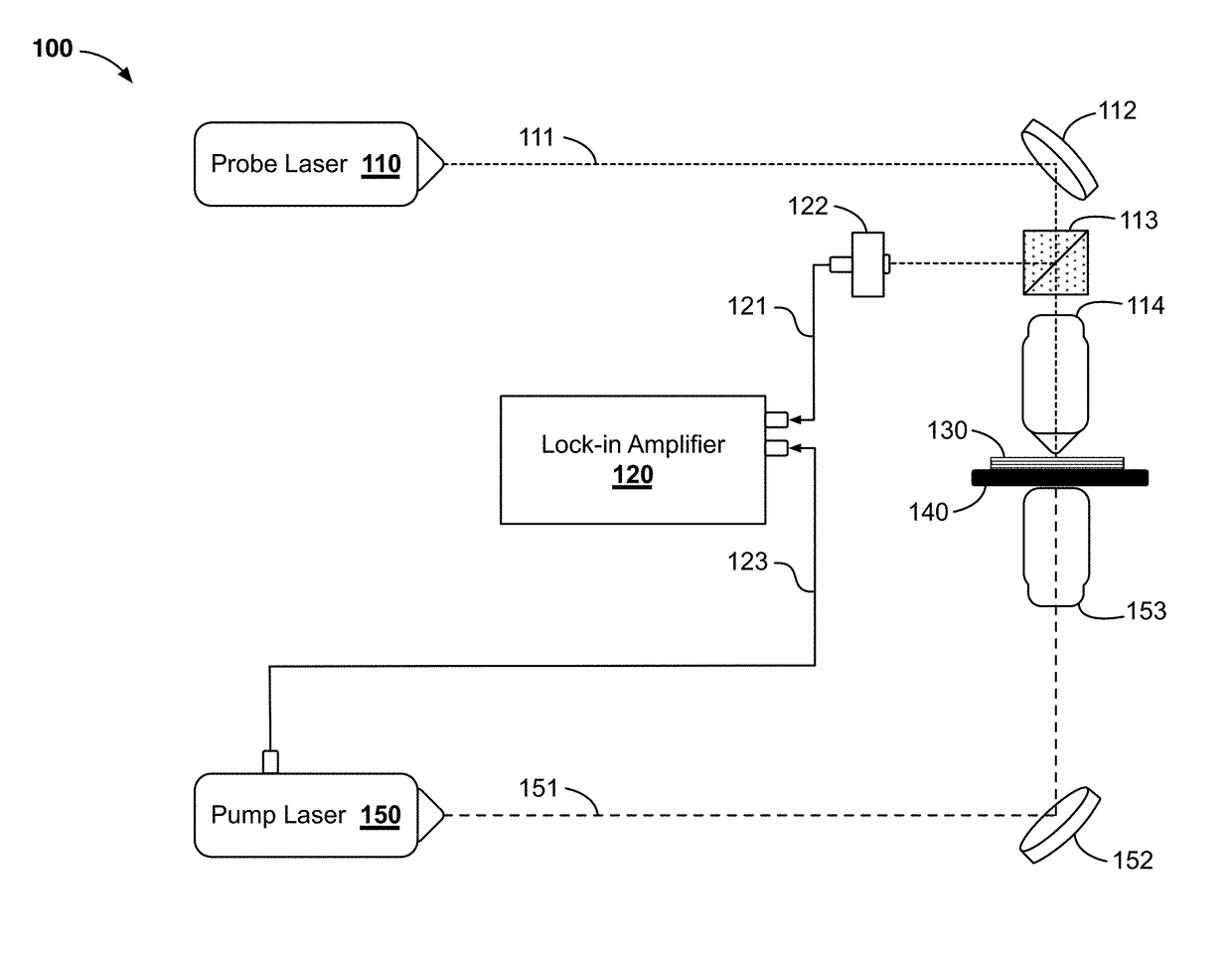
The patent text discusses the limitations of current mid-infrared imaging techniques, such as the scarcity of infrared detectors and the difficulty in achieving high spatial resolution due to the Abbe diffraction limit. The technical problem addressed in the patent is how to improve the resolution of mid-infrared imaging to enable the detection of sub-micron structures. The patent proposes a new method that integrates a scanning probe microscope with a mid-infrared imaging system to overcome these limitations.

Problems solved by technology

Other biological system imaging techniques, such as fluorescence imaging, suffer from photo-bleaching and phototoxicity effects.
Although mid-IR imaging can be a powerful tool, there are some drawbacks inherent to the physical nature of mid-IR light and mid-IR devices.
One difficulty in mid-IR imaging is the scarcity of the infrared detectors.
Thermal detectors are typically affordable, but slow and sometimes inaccurate.
Photonic detectors, on the other hand, have better read out speed and accuracy compared to thermal detectors, but are usually expensive and require an extremely low temperature to function (e.g. −203° C.).
Commonly used indium antimonide (InSb) or mercury cadmium telluride (MCT) detectors usually requires a liquid nitrogen (LN2) or thermoelectric (TE) cooling system, which make them inconvenient to use and economically undesired.
Typical mid-infrared imaging techniques also tend to have limited spatial resolution, due to the Abbe diffraction limit.
The spatial resolution of a specific color of light is linearly dependent on its wavelength, such that longer wavelengths lead to lower spatial resolution.
However, analysis of nano-scale structures is usually not possible with conventional MIR techniques.
Due to these physical limitations, imaging submicron-sized objects using mid-IR light has been infeasible in existing imaging systems.
However, those methods rely heavily on integration of sophisticated instruments and they deprive MIR measurement of its potential to be performed in media.
At the same time, the cumbersome (cooling needed), expensive and less reliable MIR detectors are in the standard configuration of those methods.
Although advances have been made with the methods described above, those techniques rely heavily upon the integration of sophisticated instrumentations, which results in complex experimental setups.
Also, none of the approaches above overcomes the difficulty of detector sensitivity.

Method used


Image

  • Photothermal imaging device and system
  • Photothermal imaging device and system
  • Photothermal imaging device and system

Examples


Embodiment Construction

[0026]The following description of example methods and apparatus is not intended to limit the scope of the description to the precise form or forms detailed herein. Instead the following description is intended to be illustrative so that others may follow its teachings.

[0027]Mid-infrared radiation is resonant to the vibrational excitations of many chemical bonds and can, therefore, its absorption spectra reveal a wealth of information of molecular composition. When MIR spectroscopy is performed in a localized area, identifying, characterizing and tracking microscopic objects become accessible. Databases of MIR spectra enable analysis of complex structures, such as single live cells and individual protein complexes. Since MIR spectroscopy reflects the vibrations of chemical bonds, the unique combination of different chemical bonds in a molecule gives rise to a characteristic spectral “fingerprint.” This circumvents the common procedures of applying stains, fixatives, or exogenous flu...


PUM


Abstract

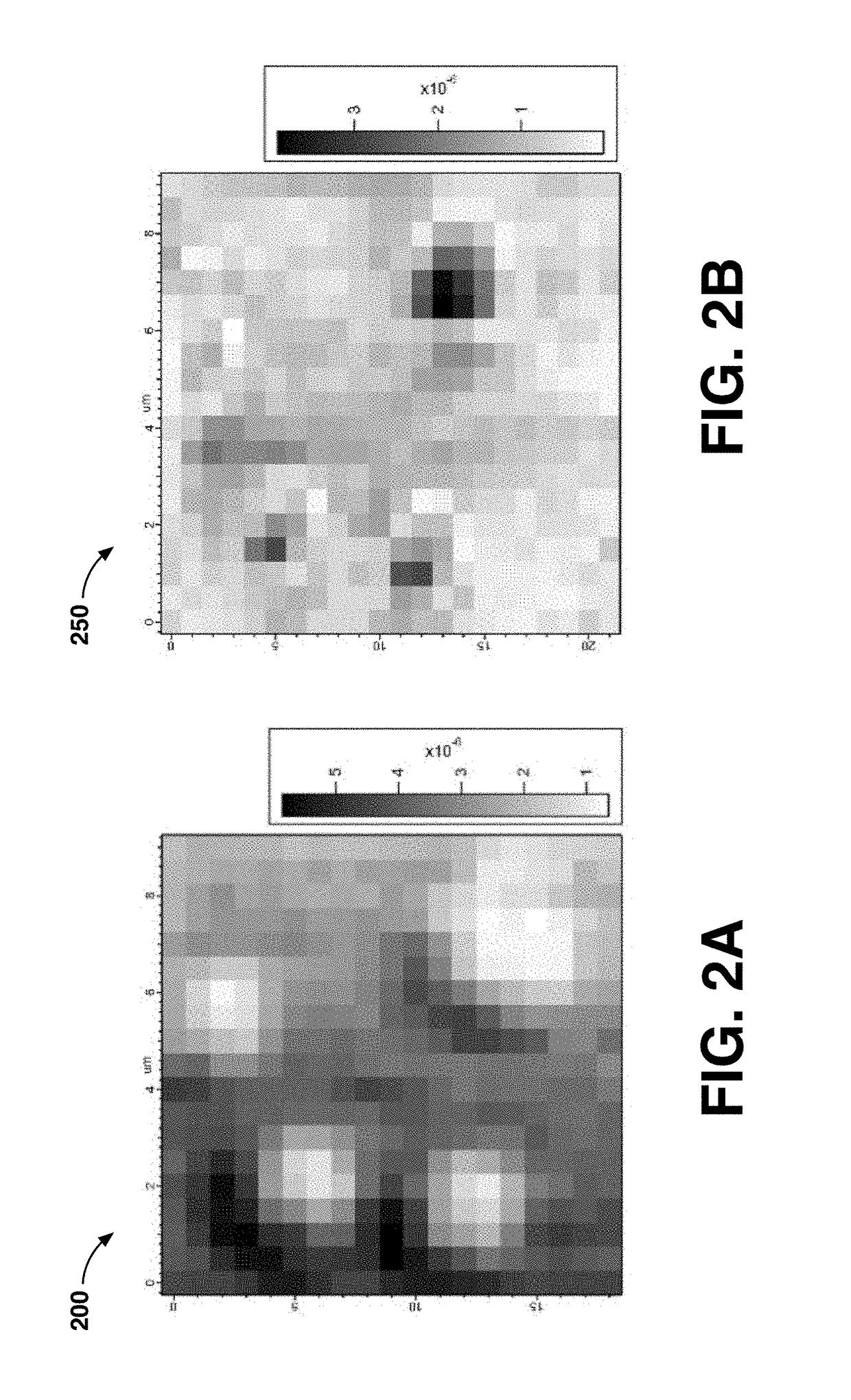
Mid-infrared photothermal heterodyne imaging (MIR-PHI) techniques described herein overcome the diffraction limit of traditional MIR imaging and uses visible photodiodes as detectors. MIR-PHI experiments are shown that achieve high sensitivity, sub-diffraction limit spatial resolution, and high acquisition speed. Sensitive, affordable, and widely applicable, photothermal imaging techniques described herein can serve as a useful imaging tool for biological systems and other submicron-scale applications.

Description

CROSS REFERENCE TO RELATED APPLICATION[0001]This application is a non-provisional application claiming priority from U.S. Provisional Application Ser. No. 62 / 318,698, filed Apr. 5, 2016, entitled “SUPER-RESOLUTION MID-INFRARED PHOTOTHERMAL IMAGING” and incorporated herein by reference in its entirety.GOVERNMENT LICENSE RIGHTS[0002]This invention was made with government support under Grant No. CHE 1110560 awarded by the National Science Foundation (NSF), Grant No. N00014-12-1-0130 awarded by the Office of Naval Research (ONR), and Grant No. W911NF-14-1-0604 awarded by the U.S. Army Research Office. The government has certain rights in the invention.FIELD OF THE DISCLOSURE[0003]The present disclosure relates generally to mid-infrared imaging. More specifically, the present disclosure relates to imaging structures and objects with a sub-micron spatial resolution using mid-infrared light.BACKGROUND OF RELATED ART[0004]Mid-infrared (mid-IR or MIR, λ=3-25 μm) light has been used as an im...

Claims


Application Information

Patent Timeline
IPC IPC(8): G01N21/3563G01Q60/34G01Q30/02G01J3/28
CPCG01N21/3563G01Q60/34G01Q30/02G01J3/2823G01N2021/1714G01N21/171G01N21/35G01N2021/1712
Inventor LI, ZHONGMINGHARTLAND, GREGORYKUNO, MASARU KEN
Owner UNIV OF NOTRE DAME DU LAC
Learn More