Antenna Unit And Wireless Power Transmission Module Including Same

a technology of wireless power transmission module and antenna unit, which is applied in the direction of transformers, inductances, transportation and packaging, etc., can solve the problems of performance degradation of other antennas than wireless power transmission antennas, limit the number of winding turns of antenna patterns, and increase the size of wireless power transmission antenna patterns, so as to reduce the resistance value of antennas, minimize heat generation, and easy to adjust

Active Publication Date: 2018-08-30
AMOTECH
View PDF6 Cites 14 Cited by
  • Summary
  • Abstract
  • Description
  • Claims
  • Application Information

AI Technical Summary

Benefits of technology

[0030]According to the present disclosure, since the line widths of the windings constituting the antenna pattern are different from each other and thus the resistance value of the antenna is reduced, it is possible to minimize the heat generation amount during the wireless power transmission while satisfying the specifications of the antenna.
[0031]In addition, by forming the pattern of the inner windings of the antenna to be thinner than the pattern of the outer windings of the antenna, a free space can be secured on the inner side of the antenna. Thus, the inductance, the outer and inner diameters, and the arrangement of the antenna can be easily adjusted, which can enhance a degree of freedom of antenna design.

Problems solved by technology

Recently, however, as a problem of a heat generation during wireless charging has increased, a design of antenna pattern to minimize the heat generation is required.
However, since the number of winding turns of the antenna pattern is proportional to the inductance, there is a limit to reduce the number of winding turns of the antenna pattern to obtain the proper inductance.
Particularly, in a combo antenna structure in which two or more antennas such as a near field communication (NFC) antenna, a magnetic secure transmission (MST) antenna, and a wireless power transmission (a magnetic induction, or a magnetic resonance) antenna are combined, an increase in the size of the wireless power transmission antenna pattern may result in performance degradation of the antennas other than the wireless power transmission antenna.
However, for the structure, it is not so easy to implement the minimization of the resistance value of the antenna due to some restrictions on the overall thickness and size of the antenna.

Method used


Image

  • Antenna Unit And Wireless Power Transmission Module Including Same
  • Antenna Unit And Wireless Power Transmission Module Including Same
  • Antenna Unit And Wireless Power Transmission Module Including Same

Examples


Embodiment Construction

[0038]Hereinafter, exemplary embodiments of the present disclosure will be described in detail with reference to the accompanying drawings, which will be readily apparent to those skilled in the art to which the present disclosure pertains. The present disclosure may be embodied in many different forms and is not limited to the embodiments described herein. In the drawings, parts not relating to the description are omitted for clarifying the present disclosure, and the same reference numerals are assigned to the same or similar components throughout the specification.

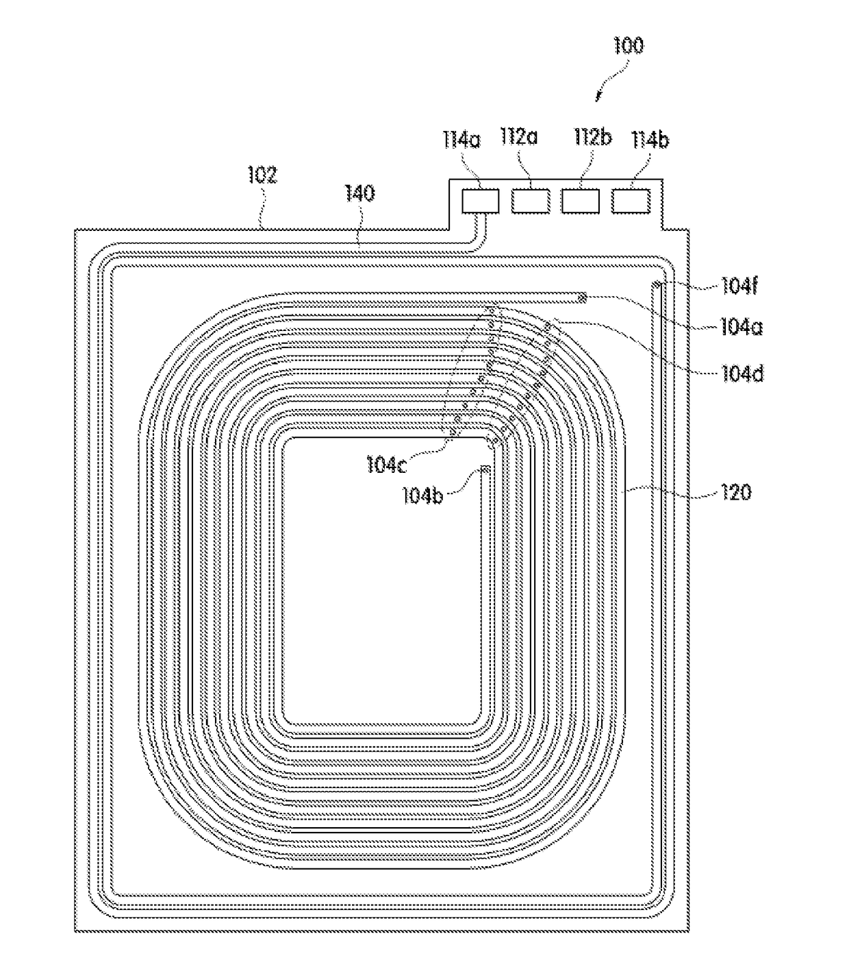
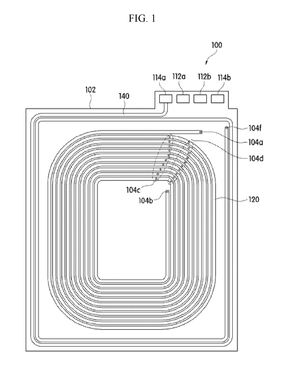
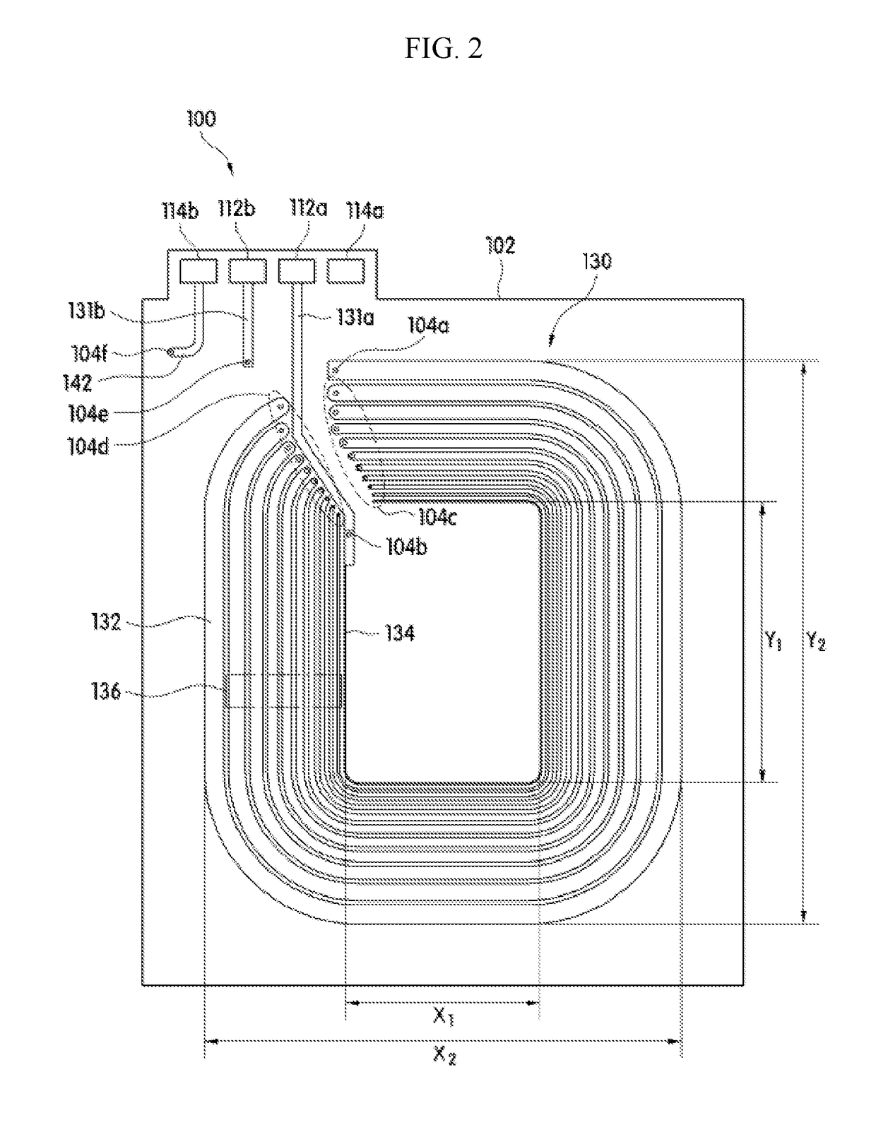
[0039]As shown in FIGS. 1 and 2, an antenna unit 100 according to an embodiment of the present disclosure may include a circuit board 102, a first antenna pattern 120, and a second antenna pattern 130.

[0040]The circuit board 102 may be a substrate having at least one antenna or a circuit unit formed optionally on an upper surface thereof. The circuit board 102 may be made from a material having a heat resistance, a pres...


PUM


Abstract

Provided are an antenna unit and a wireless power transmission module. There is provided an antenna unit that includes a circuit board, and a first antenna pattern formed on a surface of the circuit board for wireless power transmission and formed of a single conductor including a plurality of windings. The single conductor has a different line width depending on position. There is provided a wireless power transmission module that includes any one of the antenna units, and a shielding unit disposed on one surface of the antenna unit and configured to shield a magnetic field.

Description

CROSS-REFERENCE TO RELATED APPLICATION[0001]This U.S. non-provisional application claims priority under 35 USC § 119 from Korean Patent Application No. 10-2015-0117359, filed on Aug. 20, 2015 in the Korean Intellectual Property Office (KIPO), the disclosures of which are hereby incorporated by reference in their entirety.BACKGROUND1. Technical Field[0002]The present disclosure relates to an antenna unit, and more particularly, to the antenna unit and a wireless power transmission module including the same, capable of minimizing a heat generation amount during wireless power transmission.2. Discussion of the Related Art[0003]Recently, portable electronic devices such as a mobile phone, a tablet PC, and the like are equipped with a wireless communication module for wireless communication and a wireless power transmission module for wireless charging of a built-in battery. In the early days, methods for improving a charging efficiency were mainly studied. Recently, however, as a proble...

Claims


Application Information

Patent Timeline
Patent Type & Authority Applications(United States)
IPC IPC(8): H01Q1/38H01Q7/00H01Q1/52H02J7/02H02J50/10H02J50/70
CPCH01Q1/38H01Q7/00H01Q1/526H02J7/025H02J50/10H02J50/70H01Q1/02H04B5/0037H04B5/0081H01F38/14H01F27/2871H02J50/005H01F27/36H01F27/366
Inventor NOH, JIN WONBAEK, HYUNG-ILPARK, JAE-IL
Owner AMOTECH
Why Eureka
Try Eureka