Mobile robot system and method for generating map data using straight lines extracted from visual images

a robot and visual image technology, applied in image enhancement, navigation instruments, instruments, etc., can solve the problems of increasing the difficulty of localization outside, in unstructured environments such as cities, suburbs and/or villages, and the accuracy of publicly available maps for autonomous motion by robots is not high, so as to increase the probability of obtaining parameters and improve the robustness of an optimization algorithm.

Active Publication Date: 2018-09-06
STARSHIP TECH OU
View PDF7 Cites 33 Cited by
  • Summary
  • Abstract
  • Description
  • Claims
  • Application Information

AI Technical Summary

Benefits of technology

[0064]Though in the present document, the error capping method is described as a part of the mapping method, a skilled person will understand that it can be applied more generally to a wide array of optimization algorithms. It is particularly advantageous, as it can allow using standard algorithms such as the Levenberg-Marquardt ones for complex problems (such as the present mapping problem). Without the error capping method, the standard algorithm can fail or return sub-optimal results. However, it can be much more robust with this method.
[0065]In some embodiments, the method can be used to cap systematic errors comprised in sensor readings. In such embodiments, it can be used to improve the robustness of an optimization algorithm and to increase the likelihood of obtaining parameters that conform the closest to the physical system.

Problems solved by technology

Localization outdoors, in unstructured environments (such as cities, suburbs and / or villages) is a greater challenge.
First, publicly available maps are not precise enough for autonomous motion by the robot.
Second, even when the maps exist, they are likely to get outdated very fast, as new obstacles appear and old pathways disappear.
This would not be enough for localization used for autonomous robotic navigation.
Furthermore, it is not known how many landmarks there are or the type of those landmarks.
These probabilities can be almost impossible to numerically quantify.
Some of the lines are also noise.
Note that associating lines detected from camera images to landmarks can be challenging.
This set is unrestricted, and therefore very large.
That is, that the errors associated with the values that the sensors obtained are normally distributed.
However, the errors associated with sensor readings can be inherently non-Gaussian, or may contain various systematic errors due to external and internal causes.
For example, systematic errors can include the following: a constant or slowly-decaying offset; bias of the sensor in a certain direction; non-modelled or incorrectly sensed robot behaviour (for example, wheel slippage can result in erroneous odometry reading); incorrect feature association to a landmark (for example, a line extracted from a camera image can be associated to a wrong landmark); sensor reading timing offset (a sensor reading can actually be from a time before or after the sensor-reported time); incorrect calibration of a sensor; change of sensor orientation within the robot reference frame due to the robot flexing during movement or due to vibration; sensor misbehaving due to external environmental factors (for example, magnetometer readings can be unreliable when the robot passes close by a large metal object or an electrical conduit); sensor misbehaving due to inherent problems or defects in its design or manufacture etc.
These sensor reading errors can result in outliers that can severely distort the sum S(M), resulting in an incorrect map, or even in a complete failure of the optimization algorithms.
However, it is not known which readings are normal and which contain systematic errors; therefore, to avoid failure of the algorithm or producing the wrong maps, a technique for capping the sensor errors can be used.
Without the error capping method, the standard algorithm can fail or return sub-optimal results.
The current invention can be applied to self-driving cars, however, the technology presently used for self-driving cars can be cumbersome and impractical to use on a mobile delivery robot operating on sidewalks.

Method used


Image

  • Mobile robot system and method for generating map data using straight lines extracted from visual images
  • Mobile robot system and method for generating map data using straight lines extracted from visual images
  • Mobile robot system and method for generating map data using straight lines extracted from visual images

Examples


Embodiment Construction

[0115]In the following, exemplary embodiments of the invention will be described, referring to the figures. These examples are provided to provide further understanding of the invention, without limiting its scope.

[0116]In the following description, a series of features and / or steps are described. The skilled person will appreciate that unless required by the context, the order of features and steps is not critical for the resulting configuration and its effect. Further, it will be apparent to the skilled person that irrespective of the order of features and steps, the presence or absence of time delay between steps, can be present between some or all of the described steps.

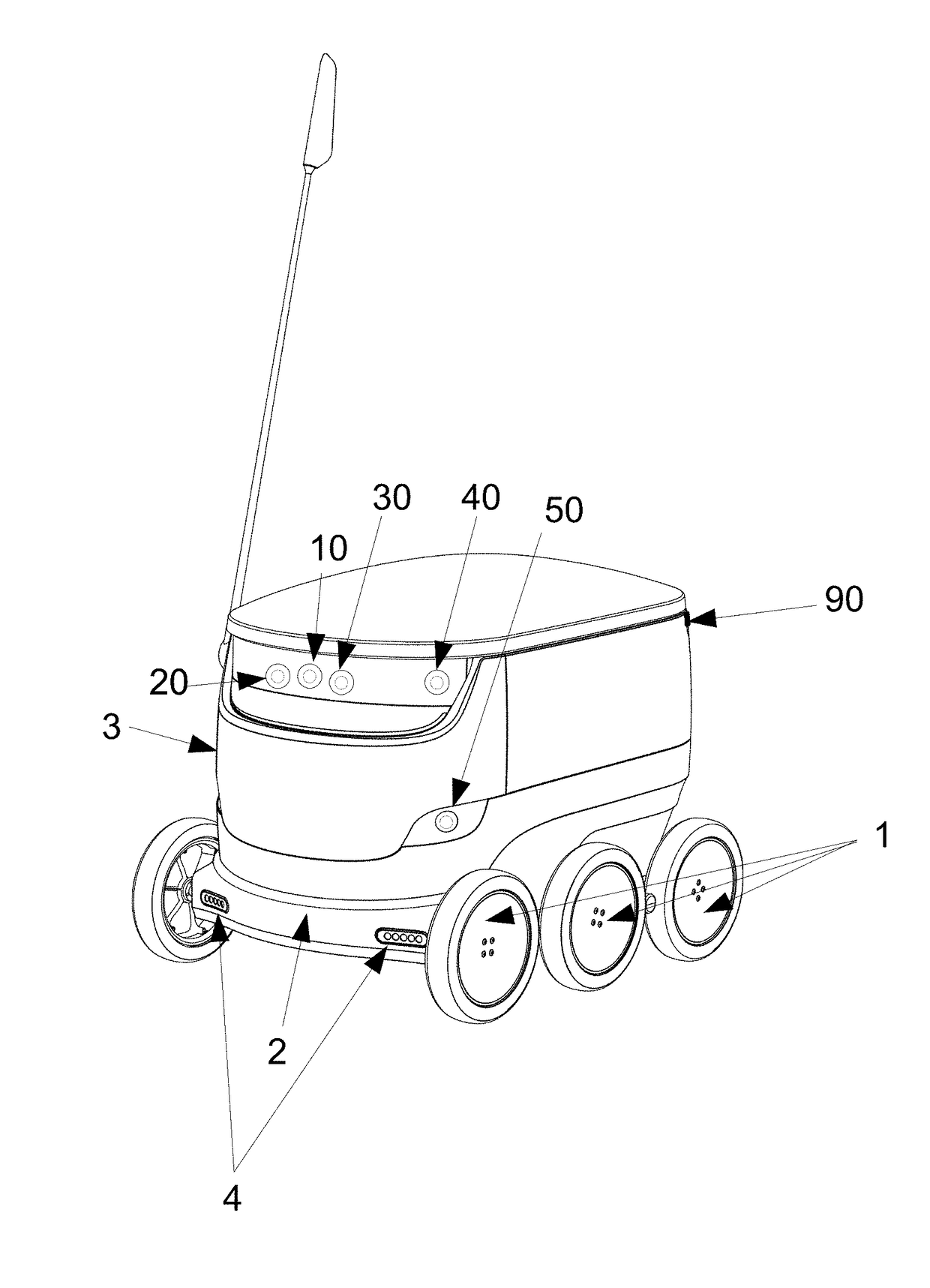
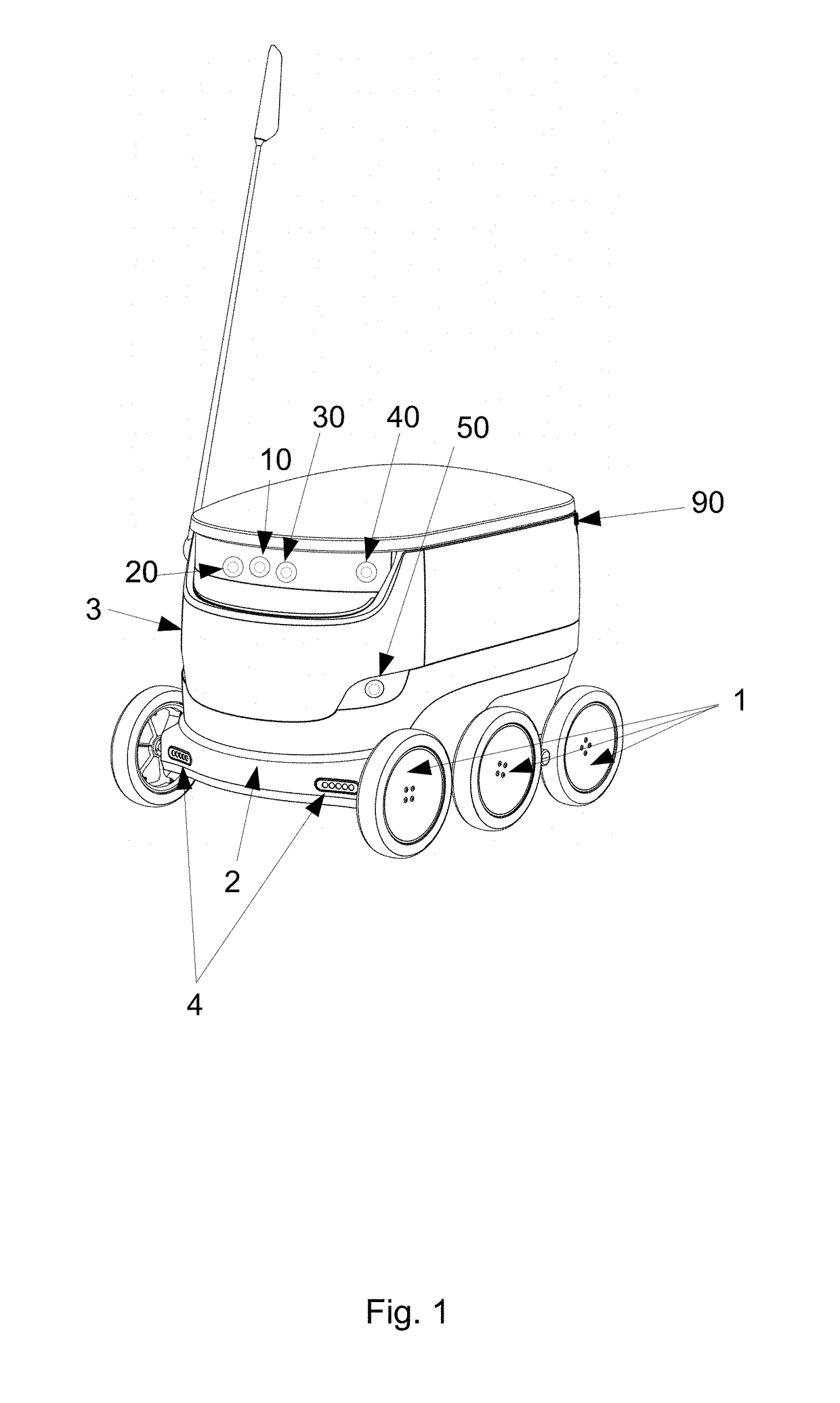
[0117]FIG. 1 shows an embodiment of the robot according to the invention. The robot comprises wheels 1 adapted for land-based motion. Frame 2 can be mounted on the wheels 1. Body 3 can be mounted on the frame 2. Body 3 can comprise an enclosed space (not shown) adapted to transport a delivery. Lights 4 can be pla...


PUM


Abstract

A mobile robot is configured to navigate on a sidewalk and deliver a delivery to a predetermined location. The robot has a body and an enclosed space within the body for storing the delivery during transit. At least two cameras are mounted on the robot body and are adapted to take visual images of an operating area. A processing component is adapted to extract straight lines from the visual images taken by the cameras and generate map data based at least partially on the images. A communication component is adapted to send and receive image and/or map data. A mapping system includes at least two such mobile robots, with the communication component of each robot adapted to send and receive image data and/or map data to the other robot. A method involves operating such a mobile robot in an area of interest in which deliveries are to be made.

Description

RELATED APPLICATIONS[0001]This is a Bypass Continuation of International Application No. PCT / EP2016 / 076466, filed Nov. 2, 2016 and published as WO 2017 / 076928A1, which claims priority to European Patent Application no. EP 15192649.0, filed Nov. 2, 2015. The contents of the aforementioned applications are incorporated by reference in their entirety.FIELD[0002]The invention relates to mapping performed by a moving robot. More particularly, the invention relates to mapping using multiple cameras taking visual images.INTRODUCTION[0003]Mapping done by mobile robots and localization of mobile robots has been an active area of research since progress in robotics allowed for semi-autonomous and autonomous robots. A moving robot must have a method of at least estimating its position in space to continue motion with a purpose. The modern framework of mapping localisation comprises a coordinate system with respect to which the localization is done and a pose, which is a combination of position...

Claims


Application Information

Patent Timeline
Patent Type & Authority Applications(United States)
IPC IPC(8): G05D1/02G05D1/00G01C21/32G06Q10/08G06T7/73G06T7/00
CPCG05D1/0251G05D1/0212G05D1/0088G01C21/32G06T2207/20212G05D1/0274G06T7/97G05D2201/0216G06T2207/10004G06Q10/0833G06T7/73G05D2201/0213G06T2207/10016G06T2207/30244G06T2207/30252G06T7/579G01C21/3848G05D1/0223G05D1/024G05D1/0246G05D1/0255G05D1/027G05D1/0272G05D1/0278
Inventor HEINLA, AHTIVOLKOV, KALLE-RASMUSROBERTS, LINDSAYMANDRE, INDREK
Owner STARSHIP TECH OU
Why Eureka
Try Eureka