Optical imaging system and methods thereof

a technology of optical imaging and optical imaging, applied in the field of optical imaging systems and methods, can solve the problems of not offering advanced optical imaging capabilities, unable to deliver robust integration of multiple images, and current imaging techniques, such as those used in the medical field, to achieve the effect of delivering multiple image integration, and reducing the number of images

Active Publication Date: 2018-09-20
THE UNIVERSITY OF AKRON
View PDF4 Cites 119 Cited by
  • Summary
  • Abstract
  • Description
  • Claims
  • Application Information

AI Technical Summary

Benefits of technology

[0023]It is another aspect of the optical imaging system of the present invention to provide projection quality monitoring, projection optimization and least-squares errors are implemented, and the accuracy of projection is updated accordingly.

Problems solved by technology

Current imaging techniques, such as those used in the medical field, still fail to deliver robust integration of multiple images, as desired by healthcare professionals, such as surgeons.
For example, surface topography measurements are currently conducted using 3D scanning methods, such as that utilized by a structured light three-dimensional (3D) scanner, which do not offer advanced optical imaging capabilities, such as that provided by fluorescence imaging or polarization imaging.
While 3D scanning based imaging methods provide surface information, topography data, 3D point cloud data, and the ability to track objects and their movements, 3D scanning only provides limited biomedical applications and diagnostic information.
Alternatively, biomedical optical imaging methods typically involve the use of planar imaging methods, and do not provide surface topography information.
In addition, such planar imaging information is difficult to fuse or combine with other imaging information, such as computerized tomography (CT) or magnetic resonance imaging (MRI) data.
The lack of 3D shape information from current optical imaging systems, such as a fluorescence imaging system, makes the registration between optical imaging and other imaging modalities difficult.
For example, typical planar fluorescence imaging is not able to acquire adequate depth / topography information from a target of interest, such as a surgical site.
Fluorescence tomography is very slow and is unable to be used for intraoperative imaging, and to track tissue deformation.
Furthermore, it is difficult to co-register fluorescence imaging with preoperative imaging data from a CT, an MRI, or positron emission tomography (PET).

Method used


Image

  • Optical imaging system and methods thereof
  • Optical imaging system and methods thereof
  • Optical imaging system and methods thereof

Examples


Embodiment Construction

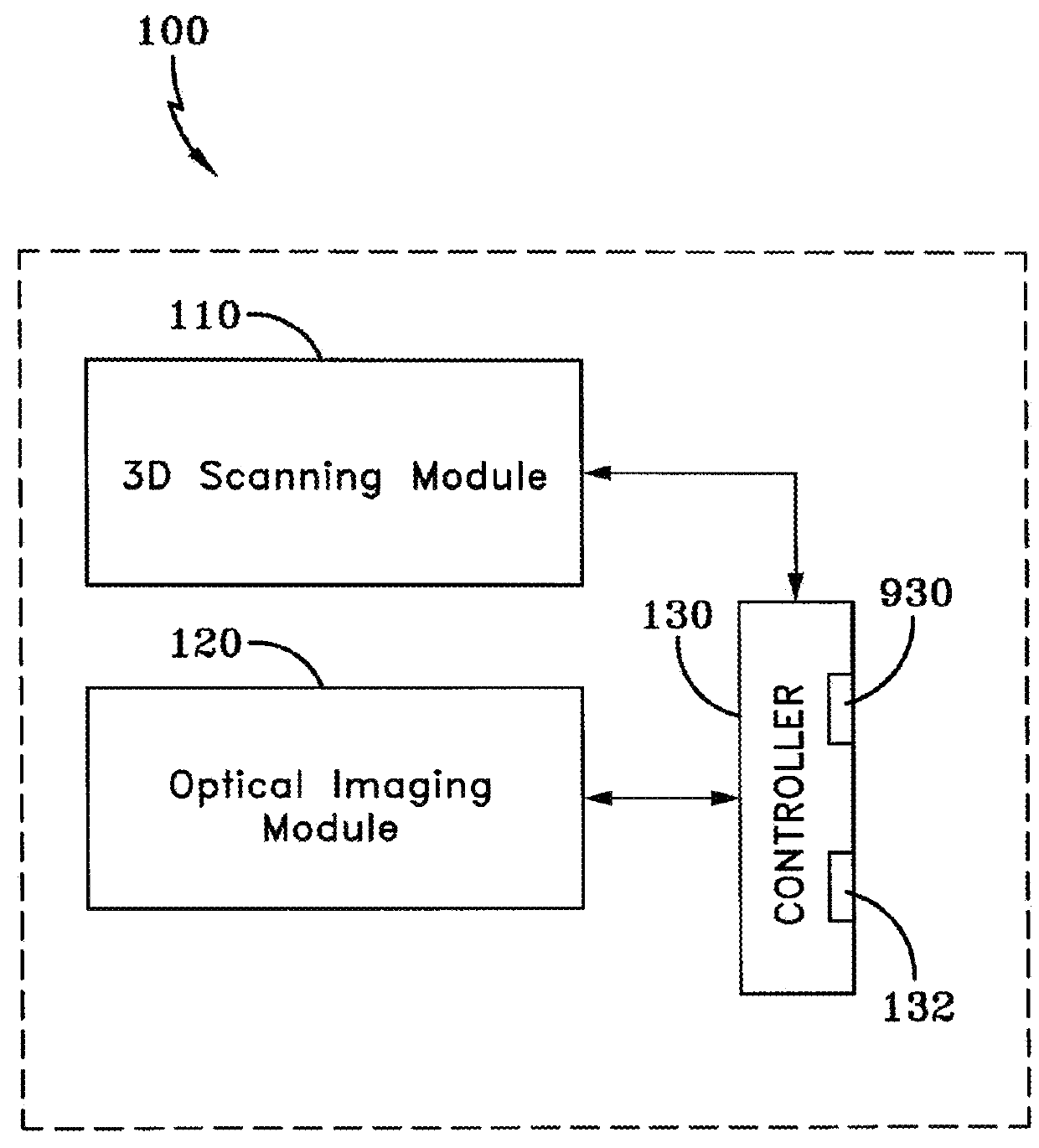
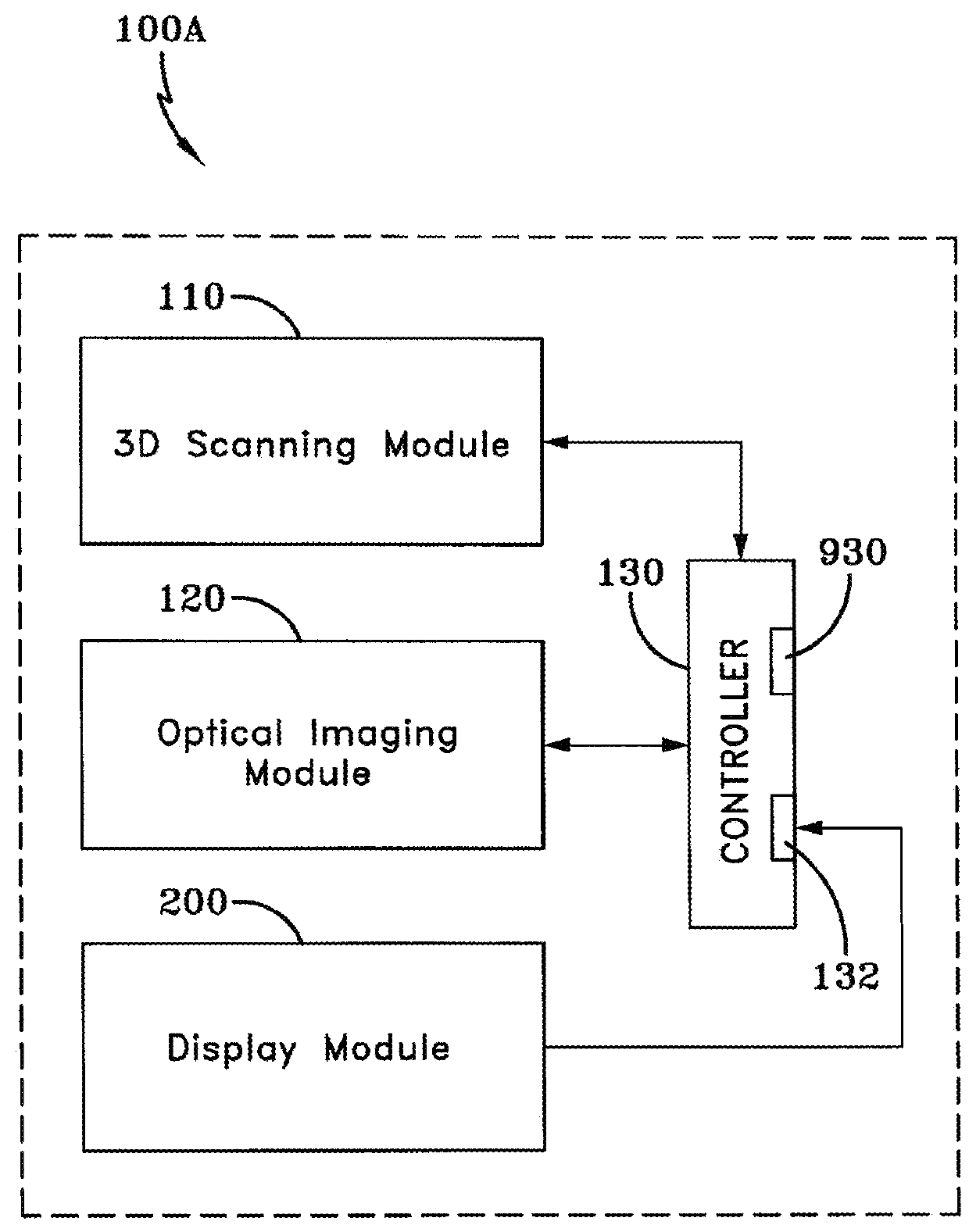
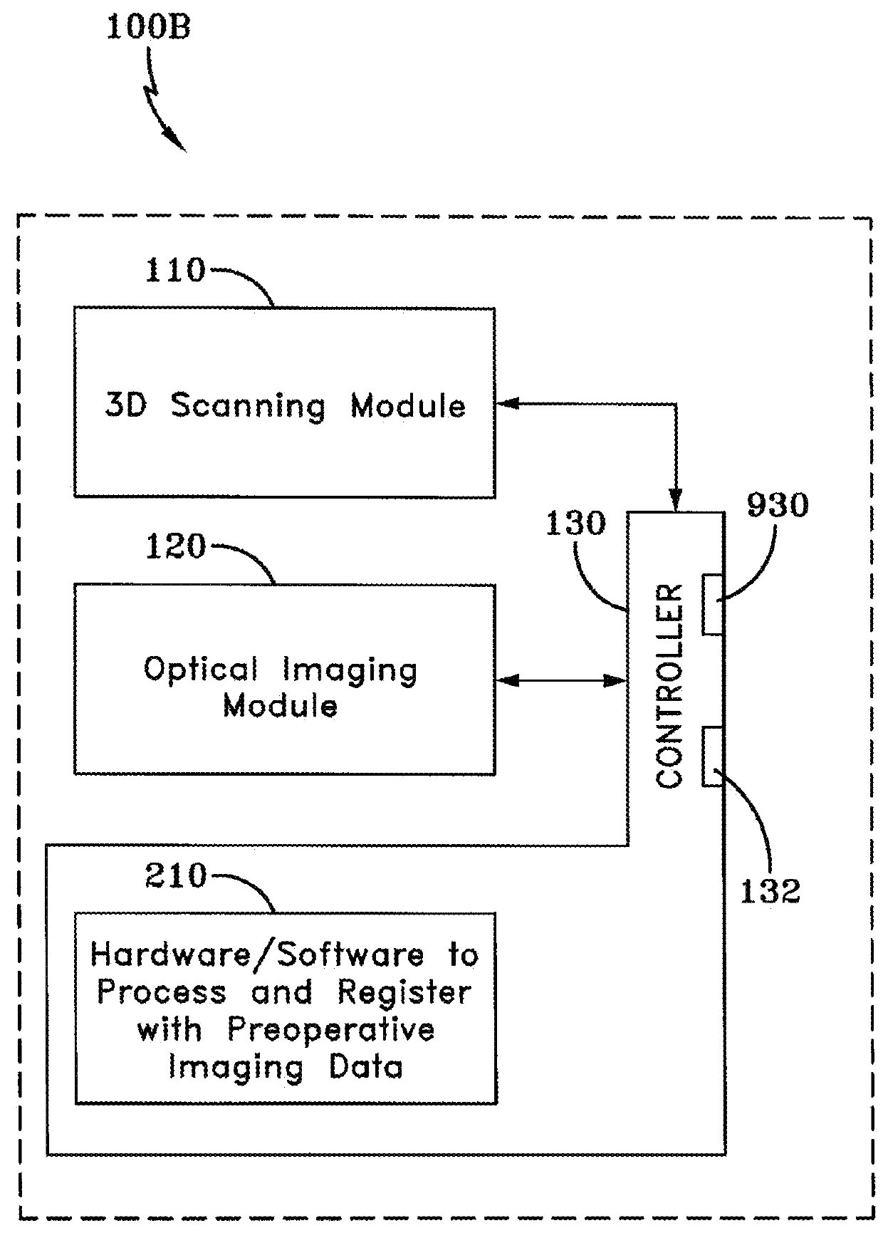
[0090]An optical imaging system of the present invention is generally referred to by numeral 100, as shown in FIG. 1 of the drawings. In particular, the imaging system 100 includes a 3D scanning module 110 and an optical imaging module 120, which are in operative communication with one another via any suitable controller 130.

[0091]The 3D scanning module 110 includes one more technologies, including but not limited to laser scanning triangulation, structured light, time-of-flight, conoscopic holography, modulated light, stereo-camera, Fourier 3D scanning, low coherence interferometry, common-path interference 3D scanning, and contact profilometers.

[0092]The optical imaging module 120 includes one or more technologies, including but not limited to fluorescence imaging, reflectance imaging, hyperspectral imaging, IR thermal imaging, Cerenkov imaging, polarization imaging, polarization difference / ratio imaging, spectral polarization difference imaging, multiphoton imaging, second harmon...


PUM


Abstract

An optical imaging system utilizes a three-dimensional (3D) light scanner to capture topography information, color reflectance information, and fluorescence information of a target object being imaged, such as a surgical patient. The system also utilizes the topography information of the target object to perform an image mapping process to project the captured fluorescence or other intraoperative images back onto the target object with enhanced definition or sharpness. Additionally, the system utilizes the topography information of the target object to co-register two or more images, such as a color image of the target object with a fluorescence image for presentation on a display or for projection back onto the target object.

Description

CROSS-REFERENCE TO RELATED APPLICATION[0001]This application claims the benefit of U.S. Provisional Application No. 62 / 112,993 filed Feb. 6, 2015, the contents of which are incorporated herein by reference.TECHNICAL FIELD[0002]Generally, the present invention relates to systems and methods of optical imaging. In particular, the present invention relates to a system and method for performing 3D scanning, optical imaging, multi-modal imaging, and image registration and display. More particularly, the present invention relates to a system and method for utilizing 3D scanning in combination with biomedical imaging, such as optical imaging and nuclear imaging modalities, to perform diagnostic functions.BACKGROUND OF THE INVENTION[0003]Current imaging techniques, such as those used in the medical field, still fail to deliver robust integration of multiple images, as desired by healthcare professionals, such as surgeons. For example, surface topography measurements are currently conducted ...

Claims


Application Information

Patent Timeline
Patent Type & Authority Applications(United States)
IPC IPC(8): H04N13/254H04N13/246G06T7/37H04N5/33H04N13/271H04N13/296A61B1/00A61B1/045A61B1/07A61B5/055A61B6/03
CPCG06T2207/10088G06T2207/10081G06T2207/10104G06T2207/10064H04N13/246H04N13/254G06T2207/10076G06T7/37H04N5/33H04N13/271H04N13/296A61B1/00006A61B1/045A61B1/07A61B5/055A61B6/032A61B6/037G06T2207/10108A61B6/508A61B6/5247G06T2207/10028G06T2207/10072A61B5/7285A61B5/7425A61B5/0064A61B5/0071A61B5/0075G06T7/30A61B5/7445A61B90/37A61B2090/373G06V20/64G06V2201/03A61B2034/105
Inventor LIU, YANG
Owner THE UNIVERSITY OF AKRON
Why Eureka
Try Eureka