Anisotropic Biocompatible Lattice Structure

a biocompatible, anisotropic technology, applied in the direction of dental surgery, prosthesis, additive manufacturing process, etc., can solve the problem of reducing the mechanical strength of new bone formation

Active Publication Date: 2018-10-04
NANOHIVE MEDICAL LLC
View PDF4 Cites 28 Cited by
  • Summary
  • Abstract
  • Description
  • Claims
  • Application Information

AI Technical Summary

Benefits of technology

[0004]In some embodiments, the present invention provides a lattice structure that can be useful in applications including medical implants. The present invention can also provide a lattice structure with anisotropic properties that can be used in medical implants and a method of use. In some embodiments, the lattice structures disclosed herein can be used to provide structural support or mechanical spacing. In other embodiments, the lattice structures disclosed herein can provide a scaffold for bone growth.
[0007]In particular, cancellous bone has anisotropic properties and possesses different mechanical properties in different directions. For instance, bone in the spine can be more stiff in the rostral-caudal direction so that a load that would fracture the bone in the anterior to posterior direction would only cause an elastic deformation in the rostral-caudal direction. Matching an implant's properties to the surrounding bone at an implant site is important because a mismatch in strength or stiffness can have an effect on the strength of new bone growth. According to Wolff's Law, bone will adapt to the physiological stresses put on it over time, becoming stronger in response when loaded and becoming weaker when not loaded. Therefore, reducing the load that a new bone formation experiences can reduce the mechanical strength of the new bone formation.
[0008]In some embodiments, the present invention provides biocompatible structures with anisotropic properties and a method of use. In particular, some embodiments of the present invention can be characterized as having an elastic modulus in one direction and at least a second elastic modulus in another direction. Directions, as used herein, are used in reference to the three-dimensional Cartesian coordinates where the x axis and y axis are horizontal and the z axis is vertical (also described herein as the x, y and z “direction”). The elastic modulus, when used to describe a lattice, implant or structure of any kind, refers to both or either of the design elastic modulus or the actual elastic modulus. The design elastic modulus of a lattice, implant or structure is the elastic modulus calculated based on its structural configuration and its material composition. The actual elastic modulus refers to the elastic modulus of a lattice, implant or structure after it has been manufactured. The actual elastic modulus can vary from the design elastic modulus due to changes or variations within manufacturing tolerances. For example, a lattice, implant or structure that is overbuilt within an acceptable tolerance during manufacturing could have a higher actual elastic modulus than the design elastic modulus. In many situations, the actual elastic modulus can be calculated using a correction factor, creating an approximate actual elastic modulus. An approximate actual elastic modulus generally quantifies the expected actual elastic modulus of a lattice, implant or structure when testing of a manufactured article has not been completed. Since a lattice, implant or structure of any kind can be easily designed using a design elastic modulus or to an approximate actual elastic modulus through the application of a correction factor, the use of the term “elastic modulus” herein can refer to both or either design parameter.
[0013]The disclosed embodiments of the present invention can be used in a method of reducing stress shielding. It can be especially beneficial to reduce stress shielding in spinal fusion procedures. The anisotropic unit cells of the present invention can be repeated to form an anisotropic lattice or scaffold for use in spinal fusion procedures. The anisotropic lattice can provide mechanical spacing between the endplates of the adjacent vertebrae and provide a scaffold for bone growth. The anisotropic properties of the present invention can allow a reduced elastic modulus in the superior to inferior direction, allowing new bone growth to be subject to physiological forces of the load-bearing spine. The reduction in stress shielding can result in stronger new bone growth.
[0014]The anisotropic properties may allow reduced stiffness in one or more directions of bone growth while possessing the requisite stiffness in one or more directions of off-axis biomechanical loading and loading required for device testing. When elongating a unit cell in a direction, the elongation can change the strut angle and decrease the stiffness of the unit cell in a direction normal to the elongation.

Problems solved by technology

Therefore, reducing the load that a new bone formation experiences can reduce the mechanical strength of the new bone formation.

Method used


Image

  • Anisotropic Biocompatible Lattice Structure
  • Anisotropic Biocompatible Lattice Structure
  • Anisotropic Biocompatible Lattice Structure

Examples


first embodiment

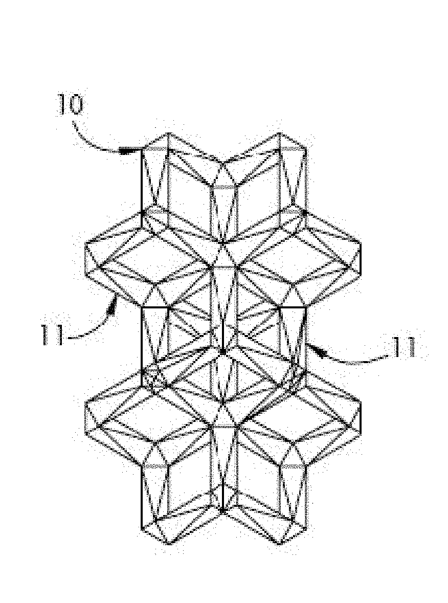
[0132]FIGS. 4-6 show a repeatable unit cell structure of the present invention. The first embodiment is an elongated MRDD lattice 110 where the shape of the unit cells is defined by struts 111. The first embodiment is a single complete elongated RDD cell with additional struts extending outward that represent portions of a repeating structure. In FIG. 4 is an isometric view, in FIG. 5 is a front view and in FIG. 6 is a bottom view of the elongated MRDD lattice 110. The side views and back view are substantially the same as the front view. The top view is substantially the same as the bottom view.

[0133]In the elongated MRDD lattice 110, each unit cell is the intersection of elongated modified rhombic dodecahedrons defined by twelve sides in the shape of rhombuses. Because the elongated MRDD lattice 110 has an open cell structure, each side of the unit cell is defined by four struts 111 that form a rhombus in a flat plane. The elongated MRDD lattice 110 is elongated in the x and y dir...


PUM

PropertyMeasurementUnit
elastic modulusaaaaaaaaaa

Abstract

The three-dimensional lattice structures disclosed herein have applications including use in medical implants. Some examples of the lattice structure are structural in that they can be used to provide structural support or mechanical spacing. In some examples, the lattice can be configured as a scaffold to support bone or tissue growth. Some examples can use a repeating modified rhombic dodecahedron or radial dodeca-rhombus unit cell. The lattice structures are also capable of providing a lattice structure with anisotropic properties to better suit the lattice for its intended purpose.

Description

CROSS REFERENCE TO RELATED APPLICATIONS[0001]This application claims the benefit of U.S. Provisional Patent Application No. 62 / 480,383 filed Apr. 1, 2017, U.S. Provisional Patent Application No. 62 / 480,393 filed Apr. 1, 2017, and U.S. Provisional Patent Application No. 62 / 619,260 filed Jan. 19, 2018, which are hereby incorporated by reference in its entirety.FIELD OF THE INVENTION[0002]The present invention relates to structures used in medical implants and, in particular, to structures characterized as a three-dimensional lattice or scaffold.BACKGROUND OF THE INVENTION[0003]Medical implants can be constructed using a wide range of materials, including metallic materials, Polyether ether ketone (hereinafter “PEEK”), ceramic materials and various other materials or composites thereof. There are competing priorities when selecting a material for an implant in order for the implant to pass regulatory testing. Some priorities when designing an implant could include strength, stiffness, ...

Claims


Application Information

Patent Timeline
Patent Type & Authority Applications(United States)
IPC IPC(8): A61F2/28A61L27/56A61L27/50A61F2/30
CPCA61F2/2846A61L27/56A61L27/505A61F2/30907A61L2430/02A61F2002/30919A61F2002/30914A61F2002/30006A61F2002/30018A61F2002/30014A61C8/0013B33Y80/00A61F2/28A61F2002/2835A61F2002/30146A61F2002/30154A61F2/4455A61F2002/3014A61F2/3094A61F2240/001A61F2002/3092A61F2210/0057A61F2002/30143A61F2002/30148A61F2002/30263A61F2002/30273A61F2310/00023A61F2002/30838A61F2002/30985A61F2/30767A61F2002/3093A61F2002/30322A61F2002/3028A61C13/0019B29C64/165A61F2002/30766A61F2002/30943A61F2/30771A61F2002/0081A61F2002/30069A61F2/30942A61F2/44A61F2002/30113A61F2002/30141A61F2002/30151A61F2002/30156A61F2002/30677
Inventor JONES, CHRISTOPHER L.HELMAR, IANDIEHL, LUCASTINLEY, JASONCHAPPUIS, KEVIN D.SULLIVAN, JOHN F.
Owner NANOHIVE MEDICAL LLC
Why Eureka
Try Eureka