Three-dimensional beam forming x-ray source

a three-dimensional beam and x-ray source technology, applied in the direction of x-ray tube target geometry, x-ray tube target and convertor, x-ray tube target and other directions, can solve the problems of small conventional x-ray sources that are sometimes used for this purpose, small useful operating life, and high cost of miniature x-ray sources, so as to facilitate the formation of x-ray beams and facilitate the generation of x-ray radiation

Active Publication Date: 2018-10-04
EMPYREAN MEDICAL SYST INC
View PDF3 Cites 9 Cited by
  • Summary
  • Abstract
  • Description
  • Claims
  • Application Information

AI Technical Summary

Benefits of technology

[0011]The target element is formed of a material responsive to the electron beam to facilitate generation of X-ray radiation when the electron beam intercepts the target element. A beam former structure is disposed proximate to the target element and comprised of a material which interacts with the X-ray radiation to form an X-ray beam. An EBG control system selectively controls at least one of a beam pattern and a direction of the X-ray beam by selectively varying a location where the electron beam intersects the target element. In some scenarios disclosed herein, the EBG control system is configured to selectively vary the location where the electron beam intercepts the target by steering the electron beam with an electron beam steering unit.
[0012]The beam former is comprised of a high-Z material which is configured to absorb a portion of the X-ray radiation to facilitate formation of the X-ray beam. The EBG control system is configured to indirectly control the portion of the X-ray beam that is absorbed by the beam-former by selectively varying the location where the electron beam intersects the target element.
[0013]According to one aspect, the beam-former is comprised of at least one shield wall. The one or more shield walls are arranged to at least partial

Problems solved by technology

Still, the very small conventional X-ray sources that are sometimes used for this purpose have been found to suffer from certain drawbacks.
One problem is that the miniature X-ray sources are very expensive.
A second problem is that they have a very limited useful operating life.
This limited useful operating life typically means that the X-ray source must be replaced after being used to perform IORT on a lim

Method used


Image

  • Three-dimensional beam forming x-ray source
  • Three-dimensional beam forming x-ray source
  • Three-dimensional beam forming x-ray source

Examples


Embodiment Construction

[0041]It will be readily understood that the solution described herein and illustrated in the appended figures could be arranged and designed in a wide variety of different configurations. Thus, the following more detailed description, as represented in the figures, is not intended to limit the scope of the present disclosure, but is merely representative of certain implementations in various different scenarios. While the various aspects are presented in drawings, the drawings are not necessarily drawn to scale unless specifically indicated.

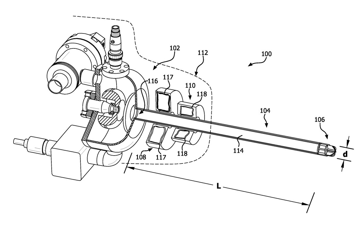
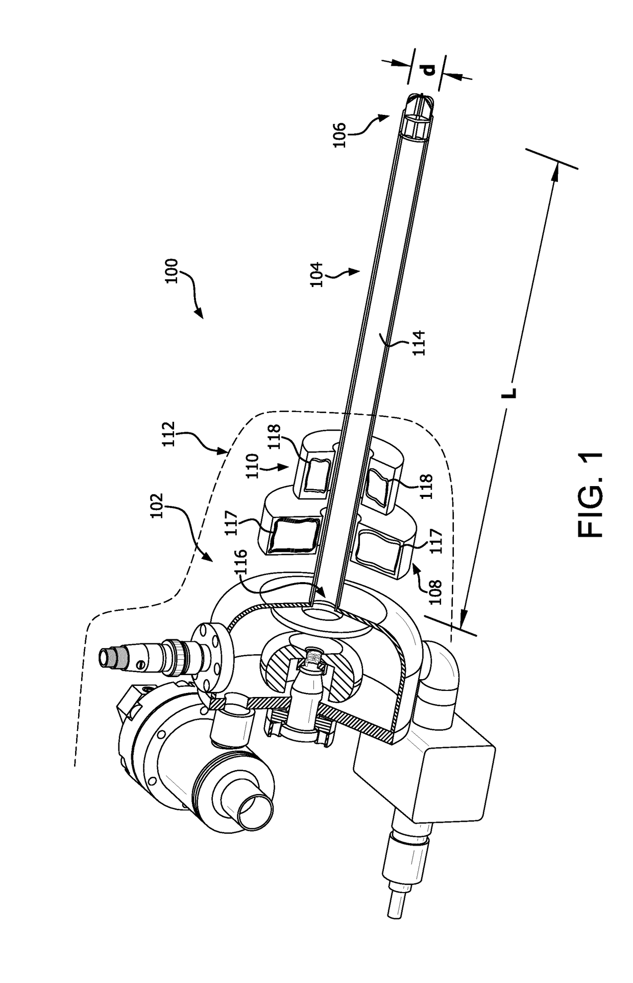
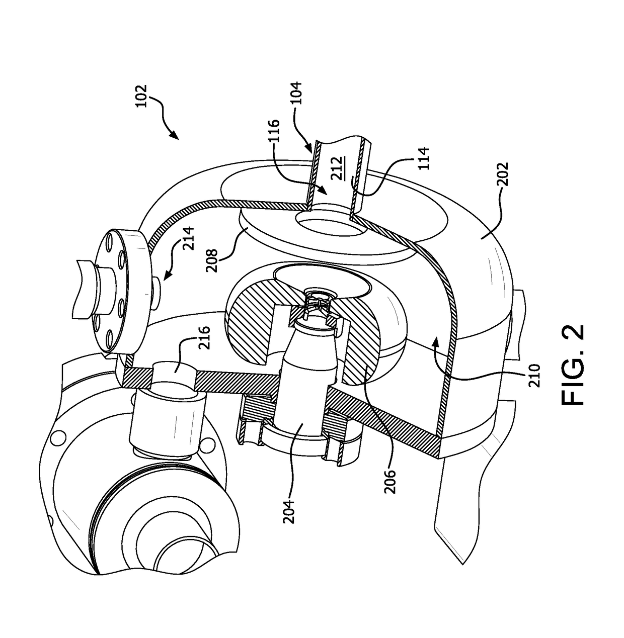
[0042]A solution disclosed herein concerns an X-ray source which can be used for treating superficial tissue structures in various radiotherapy procedures, including IORT. Drawings useful for understanding the X-ray source 100 are provided in FIGS. 1-7. With the arrangement shown in FIGS. 1-7, X-rays can be selectively directed in a plurality of different directions around a periphery of a beam directionally controlled target assembly (DCTA) 106...


PUM


Abstract

Three dimensional beam forming X-ray source includes an electron beam generator (EBG) to generate an electron beam. A target element is disposed a predetermined distance from the EBG and positioned to intercept the electron beam. The target element is responsive to the electron beam to generate X-ray radiation. A beam former is disposed proximate to the target element and comprised of a material which interacts with the X-ray radiation to form an X-ray beam. An EBG control system controls at least one of a beam pattern and a direction of the X-ray beam by selectively varying a location where the electron beam intersects the target element to control an interaction of the X-ray radiation with the beam-former.

Description

CROSS REFERENCE TO RELATED APPLICATIONS[0001]This application claims the benefit of U.S. Patent Provisional No. 62 / 479,455, filed on Mar. 31, 2017, which is hereby incorporated by reference in its entirety.BACKGROUNDStatement of the Technical Field[0002]The technical field of this disclosure comprises sources of X-ray electromagnetic radiation, and more particularly to compact sources of X-ray electromagnetic radiation.Description of the Related Art[0003]X-rays are widely used in the medical field for various purposes, such as radiotherapy. A conventional X-ray source comprises a vacuum tube which contains a cathode and an anode. A very high voltage of 50 kV up to 250 kV is applied across the cathode and the anode, and a relatively low voltage is applied to a filament to heat the cathode. The filament produces electrons (by means of thermionic emission, field emission, or similar means) and is usually formed of tungsten or some other suitable material, such as molybdenum, silver, or...

Claims


Application Information

Patent Timeline
IPC IPC(8): H01J35/14H01J35/16
CPCH01J35/14H01J35/16H01J35/30H01J35/32H01J2235/086H01J2235/166H01J35/153
Inventor FISHMAN, KALMANWILFLEY, BRIAN P.ELLENOR, CHRISTOPHER W.OLGADO, DONALDKU, CHWEN-YUANFUNK, TOBIASVATAHOV, PETREMITCHELL, CHRISTOPHER R.
Owner EMPYREAN MEDICAL SYST INC
Why Eureka
Try Eureka