Metal paste and thermoelectric module

a technology of thermoelectric modules and metal paste, which is applied in the direction of manufacturing tools, welding/cutting media/materials, and so on, can solve the problems of difficult to drive a thermoelectric module using a pb-based solder paste, the limitation of the solder paste in driving a thermoelectric module, and the inability to achieve sufficient adhesive properties, excellent thermal and electrical properties

Active Publication Date: 2018-10-04
LG CHEM LTD
View PDF11 Cites 1 Cited by
  • Summary
  • Abstract
  • Description
  • Claims
  • Application Information

AI Technical Summary

Benefits of technology

[0050]According to the present invention, a metal paste having excellent thermal and electrical properties and sufficient adhesive properties, and a thermoelectric module which adopts a bonding technique using the metal paste between a thermoelectric element and an electrode, may be provided.

Problems solved by technology

However, such a solder paste has a limitation in driving a thermoelectric module in a high-temperature condition because of its low melting point.
For example, it may be difficult to drive a thermoelectric module using an Sn-based solder paste for bonding a thermoelectric element and an electrode at a temperature of 200° C. or higher.
Further, it may be difficult to drive a thermoelectric module using a Pb-based solder paste at a temperature of 300° C. or higher.

Method used


Image

  • Metal paste and thermoelectric module
  • Metal paste and thermoelectric module
  • Metal paste and thermoelectric module

Examples


example 1

[0059](1) 27.3% by weight of Ni μmpowder (0.6 μm), 66.7% by weight of Sn powder (5-10 μm), 1% by weight of sodium stearate, and 5.0% by weight of dihydro terpineol were mixed to prepare a metal paste.

[0060](2) A thermoelectric module was prepared by using a skutterudite-based thermoelectric semiconductor as a thermoelectric material, and primary heat-drying the metal paste at 110° C. for 10 minutes, subjecting it to pressure (15 MPa) at 400° C. for 30 minutes, and bonding.

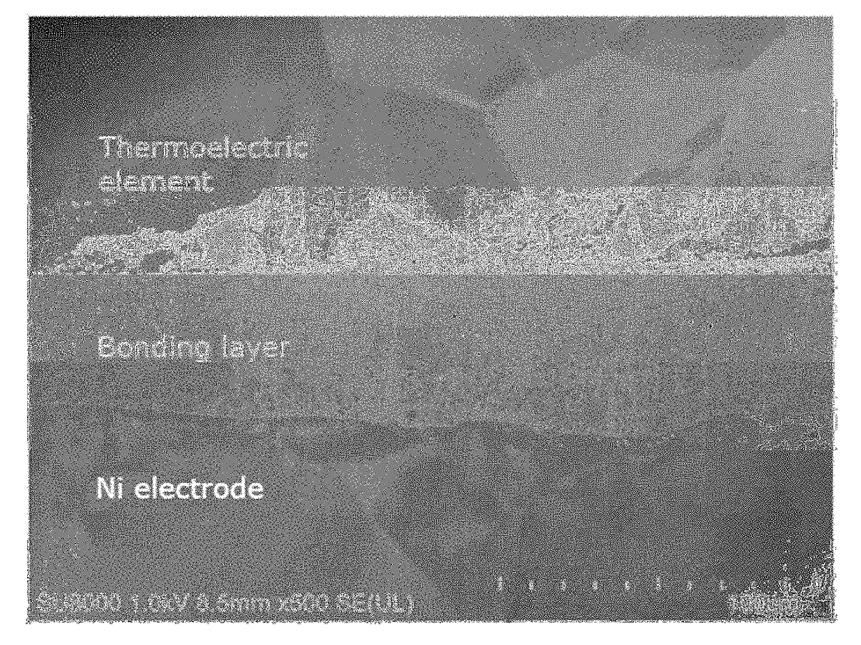
[0061](3) At this time, the substrate size of the high-temperature portion of the thermoelectric module thus prepared was 30*30 mm, the substrate size of the low-temperature portion was 30*32 mm, and the size of the element was 3*3*2 mm, and the total number of the thermoelectric module is 32 pairs. The cross-section of the thus-prepared thermoelectric module was analyzed by SEM, and the analysis image thereof is shown in FIG. 1.

example 2

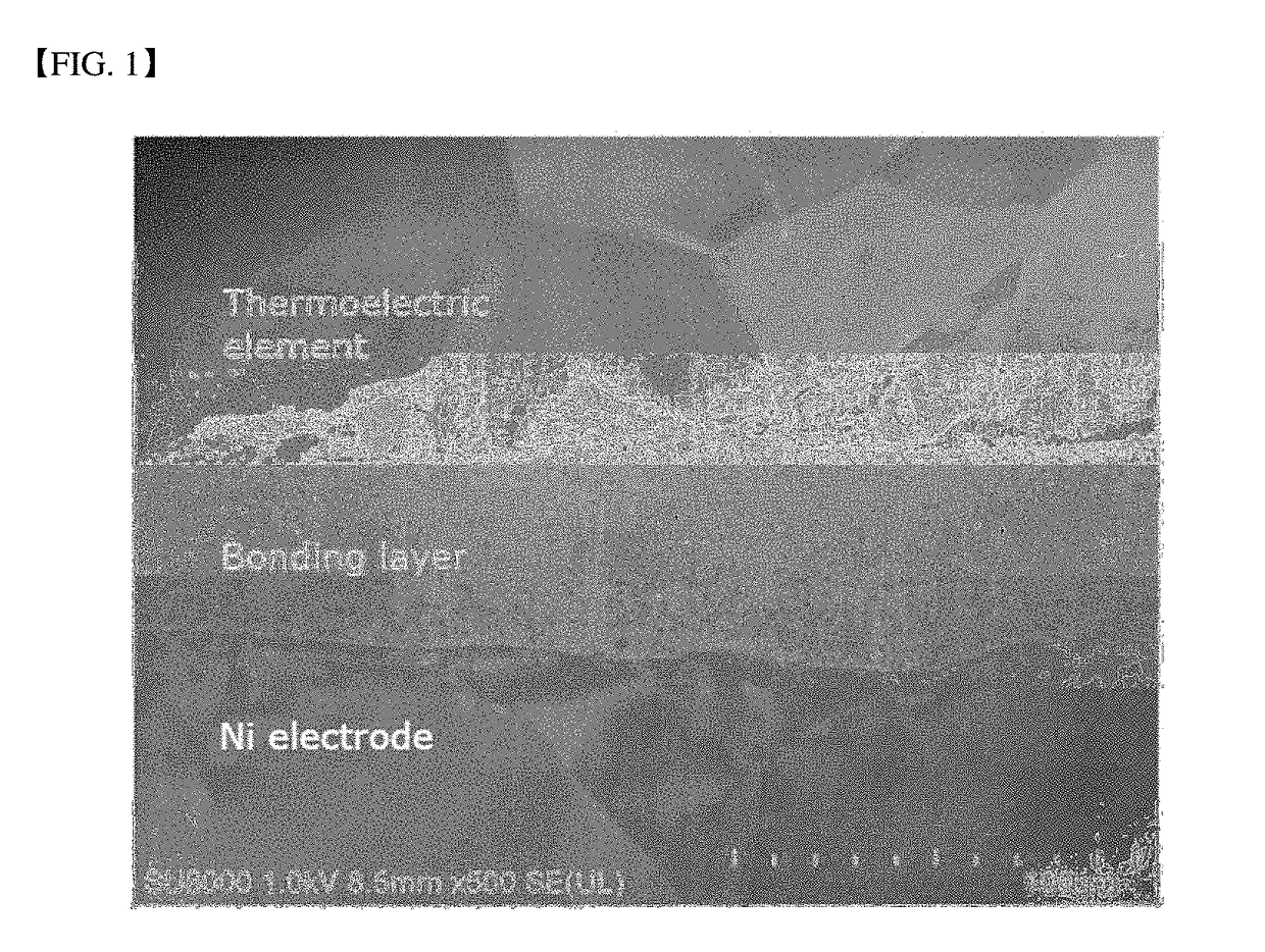
[0062]A thermoelectric module was prepared in the same manner as in Example 1, except that 27.5% by weight of Ni powder (0.6 μm), 67.5% by weight of Sn powder (2.5 μm), 1% by weight of oleylamine, and 4.0% by weight of dihydro terpineol were mixed to prepare a metal paste. The cross-section of the thus-prepared thermoelectric module was analyzed by SEM, and the analysis image thereof is shown in FIG. 2.

experimental example

[0074]The bonding layer resistivity, bonding strength, and bonding layer thermal conductivity of the thermoelectric modules prepared in Examples 1 and 2 and Comparative Examples 1 to 5 were measured by the following methods, and the results are shown in Tables 1 and 2 below.

[0075](1) Bonding strength: Instantaneous shear strength when the device ruptures from the electrode by applying a shear force to the thermoelectric device while the thermoelectric device is attached to the substrate through the metal paste was measured using a bond tester (Nordson DAGE 4000).

[0076](2) Porosity of bonding layer: Cross-sectional image of the bonding layer obtained by SEM was measured by analyzing particles using an image analysis program (Image J).

[0077](3) Resistivity of bonding layer: Resistivity value according to temperature was measured by bringing the electrode into contact with the bonding material having a predetermined standard using a resistivity measuring device (Linseis LSR-3).

[0078](4...


PUM

PropertyMeasurementUnit
particle sizeaaaaaaaaaa
boiling pointaaaaaaaaaa
porosityaaaaaaaaaa

Abstract

The present invention relates to a metal paste including: a first metal powder including nickel (Ni); a second metal powder including at least one selected from the group consisting of tin (Sn), zinc (Zn), bismuth (Bi), and indium (In); and a dispersing agent, and to a thermoelectric module which adopts a bonding technique using the metal paste.

Description

CROSS-REFERENCE TO RELATED APPLICATION(S)Technical Field[0001]This application claims the benefit of priority of Korean Patent Application No. 10-2015-0179577 filed with the Korean Intellectual Property Office on Dec. 15, 2015 and Korean Patent Application No. 10-2016-0127765 filed on Oct. 4, 2016 with the Korean Intellectual Property Office, the entire contents of which are incorporated herein by reference.[0002]The present invention relates to a metal paste having excellent thermal and electrical properties and a sufficient adhesive property, and to a thermoelectric module which adopts a bonding technique using the metal paste between a thermoelectric element and an electrode.Background Art[0003]If there is a temperature difference between both ends of materials in a solid state, a difference in the concentration of carriers (electrons or holes) having thermal dependence occurs, leading to an electrical phenomenon called a thermal electromotive force, that is, a thermoelectric eff...

Claims


Application Information

Patent Timeline
Patent Type & Authority Applications(United States)
IPC IPC(8): H01L35/08H01B1/22
CPCH01L35/08H01B1/22B23K35/262B23K35/264B23K35/282B23K35/3033B23K35/3601B23K35/0244B23K35/025B23K35/3612H10N10/817H10N10/85H10N10/851H10N10/856H10N10/853H10N10/13H10N10/01H10N10/17B23K35/3618B23K35/3603
Inventor LEE, DAE KIKIM, DONG-SIKPARK, CHEOL-HEE
Owner LG CHEM LTD
Why Eureka
Try Eureka