Exhaust gas purification device and corresponding control process

Active Publication Date: 2018-10-11
FAURECIA SYST DECHAPPEMENT
View PDF1 Cites 28 Cited by
  • Summary
  • Abstract
  • Description
  • Claims
  • Application Information

AI Technical Summary

Benefits of technology

[0014]The use of elongate heating elements with small sections makes it possible to increase the length of these elements. They can therefore be arranged on one or several planes and well distributed across from the purification member, so as to heat the upstream face or the downstream face of the purification member uniformly.
[0015]Distributing t

Problems solved by technology

Such members are only effective when the catalytic material is at a minimum temperature.
Such fastening is delicate to do at a fa

Method used


Image

  • Exhaust gas purification device and corresponding control process
  • Exhaust gas purification device and corresponding control process
  • Exhaust gas purification device and corresponding control process

Examples


Embodiment Construction

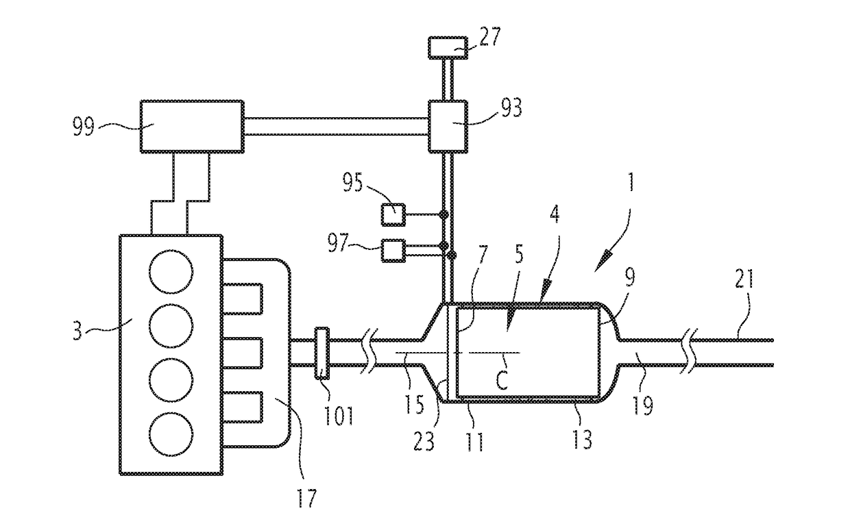
[0069]The exhaust line 1 shown in FIG. 1 is intended to be installed on board a vehicle, typically a vehicle equipped with a heat engine 3. This vehicle is typically a motor vehicle, for example a car or truck.

[0070]As shown in FIG. 1, the exhaust line 1 comprises an exhaust gas purification device 4. This device 4 includes at least one purification member 5 for purifying exhaust gases having an upstream face 7 by which the exhaust gases penetrate the purification member 5, and a downstream face 9 by which the exhaust gases leave the purification member 5.

[0071]In the present description, upstream and downstream will be understood relative to the normal direction of the exhaust gases.

[0072]The purification member 5 is for example an SCR catalyst, a three-way catalyst, an oxidation catalyst, or an NOx trap.

[0073]The purification member 5 is placed inside an enclosure 11, with an interposed maintaining layer 13. The enclosure 11 has an exhaust gas inlet 15, fluidly connected to a coll...


PUM


Abstract

A device includes a power source, at least one exhaust gas purification member having an upstream face and a downstream face, and a heating member placed in front of and at a distance from the upstream or downstream face. The heating member comprises a frame and a plurality of elongate heating elements surrounded by a peripheral part of the frame. Each heating element has first and second ends, with at least one of the first and second ends being electrically connected to the power source with the other end being connected to the frame. Each heating element is, between the first and second ends, connected only to at least one other of the heating elements. The heating elements are in contact with one another by respective points of contact, two points of contact of two different heating elements in contact with one another being at the same electric potential.

Description

CROSS-REFERENCE TO RELATED APPLICATION[0001]This application claims priority to FR 1753059, filed Apr. 7, 2017.FIELD OF INVENTION[0002]The invention generally relates to devices and methods for purifying exhaust gases from a vehicle.BACKGROUND[0003]The exhaust lines of vehicles equipped with heat engines typically comprise catalytic purification members, for example making it possible to convert NOx, CO and hydrocarbons into N2, CO2 and H2O. Such members are only effective when the catalytic material is at a minimum temperature.[0004]WO2016 / 066551 describes a purification device in which a heating member is mounted across from the upstream face of a catalyst. The heating member comprises a heating wire, fixed by pins pushed into the channels of the catalyst.[0005]Such fastening is delicate to do at a fast pace.[0006]Furthermore, such a system restricts the choice of the catalyst to be integrated (type of substrate, impregnation, etc.).[0007]In this context, a device is proposed for ...

Claims


Application Information

Patent Timeline
IPC IPC(8): F01N3/20H05B3/03H05B3/24
CPCF01N3/2013H05B3/03H05B3/24B01D53/9418B01D53/9445B01D53/944B01D53/9422H05B2203/022F01N11/005F01N2240/16F01N3/0814F01N3/0842F01N3/101F01N3/103F01N3/2066F01N3/2882F01N2530/04F01N2530/06Y02A50/20Y02T10/12Y02T10/40
Inventor BARTOLO, XAVIER
Owner FAURECIA SYST DECHAPPEMENT
Why Eureka
Try Eureka