Improved implant device

a technology of implant devices and implants, applied in the field of implant devices, can solve the problems of increasing the burden on health care expenditure, affecting the pvi, and reducing the chance of recurrence, and achieve the effect of increasing the probability of recurren

Active Publication Date: 2018-10-18
MEDICAL DEV TECH
View PDF4 Cites 0 Cited by
  • Summary
  • Abstract
  • Description
  • Claims
  • Application Information

AI Technical Summary

Benefits of technology

[0025]The method of the present invention comprises inducing a current in the ablation region of the implant device by the external energy-providing means, said current heating up the ablation region, preferably through Joule heating, to an ablation temperature, thereby creating a circumferential lesion on the vessel wall. The lesion, or the scar tissue created by the lesion, can thereby form a signal-blocking circumferential path around the vessel wall.
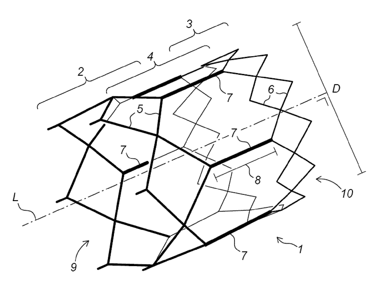
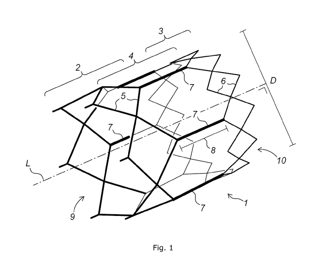
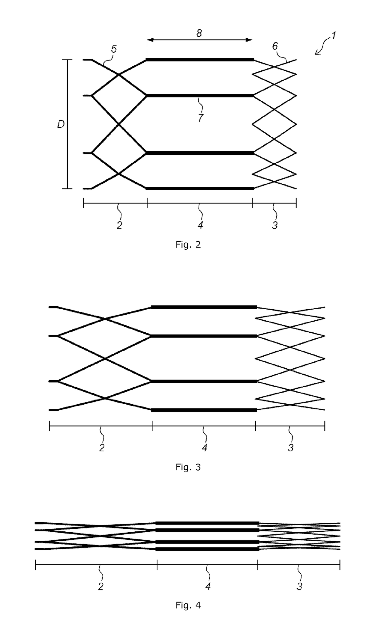
[0026]The present invention improves on the prior art, in that the ablation region of the implant device comprises a circumferential diamond-like structure, and that the implant device comprises a support structure, which is attached to the diamond-like structure of the ablation region, the ablation region being on a proximal side of the implant device and the support region being on the distal side of the implant device. The circumferential diamond-like structure of the ablation region can substantially expand radially, thereby ensuring that a complete circumferential band along the vessel's inner wall is subtended. At the same time, the circumferential diamond-like structure can effectively form a lesion of two interconnected zig-zag loops around the vessel's wall, which increases the probability of creating a circumferential signal-blocking path. Furthermore, the circumferential diamond-like structure can act as a receiving coil in which a circumferential current can be induced by a time-varying mag...

Problems solved by technology

It accounts for huge increases in morbidity and mortality.
This leads to an increased burden on the health care expenditure.
PVI is ...

Method used


Image

  • Improved implant device
  • Improved implant device
  • Improved implant device

Examples


example 1

gs

[0087]In order to illustrate the system, devices and methods of the present invention, the techniques described herein were used on pigs, using a stent-based contactless energy transfer to isolate PVs in pigs.

[0088]Hereby, nitinol self-expanding implants were positioned in the pulmonary veins of pigs. Using electromagnetic wireless energy transfer principles, implants were heated in a controlled fashion. Using an electrophysiological sensing and pacing catheter, signals were checked before and after the ablation, and conduction block persistence acutely and after one month were checked. Eleven animals were successfully treated. Implantation and wireless energy transfer were safely performed in all animals. While pacing was successful in all animals prior to the ablation, conduction block was shown acutely in all eleven animals and chronically in seven animals. No periprocedural complications occurred, and the seven chronic animals remained in excellent shape until their sacrifice ...

example 2

gs, Further Trials

[0178]A further set of pig trials was conducted along similar lines as in the previous example for map the left atrium, implanting a dedicated nitinol-based self-expanding device, ablating the dedicated heating ring, remapping the left atrium after application of the ablation technology and evaluating acute histology.

[0179]In the procedure, the pigs are prepared and anesthetized. Catheterization is performed via a left intercostal incision.

[0180]During the procedure:[0181]one 6F sheath (to allow for the temperature optic sensors), one 8.5F Zurpaz (Boston Scientific) steerable guide or a 9F introducer, and one 6F sheath will be introduced into the left atrium;[0182]initial contrast fluid will be injected to image the left atrium and PV structure;[0183]a 10-pole stimulation or pacing catheter shall be positioned into the PV distal from the target ablation zone;[0184]signals in the PV will be measured;[0185]pacing will be performed at a fixed rate above the pigs basic...


PUM


Abstract

The present invention concerns a self-expanding implant device comprising a proximal portion at a first longitudinal end, a distal portion at a second longitudinal opposite the first longitudinal end, and a connecting portion between the proximal portion and the distal portion, wherein the proximal portion and the distal portion each comprise a radially self-expanding structure, wherein the connecting portion comprises longitudinally oriented bendable struts, preferably at least 4 struts, more preferably 6 struts or more, which connect the self-expanding structure of the proximal portion with the self-expanding structure of the distal portion, wherein in a fully expanded state, the implant device comprises a maximum implant diameter along a direction perpendicular to the longitudinal direction and wherein the struts of the connecting portion comprise a strut length along the longitudinal direction, characterized in that the strut length is such that when the self-expanding structure of the proximal portion is in a compacted state and the self-expanding structure of the distal portion is not constrained radially, the self-expanding structure of the distal portion reaches a semi-expanded state comprising a diameter which is at least 60% of the maximum implant diameter.

Description

TECHNICAL FIELD[0001]The present invention concerns implant devices, such as stent devices, which can be implanted in vessels and organs. More in particular, the implant devices of the present invention are particularly apt in correctly being placed at a chosen location within the vessel or organ, and this preferably to provide treatment to the walls of the vessel or organ.BACKGROUND[0002]Implant devices such as stents are typically placed in vessels, e.g. arteries or veins, to keep the vessel open.[0003]Implant devices can also be used to provide local treatment, e.g. to treat the surrounding tissue. An example of a system and implant device for local treatment is disclosed in document WO 2012 / 131107 A1. Herein a system is disclosed comprising an implant device and external energy-providing means. The system is particularly developed for ablation of a vessel's wall from the inside, more specifically the system comprises implant devices which can be placed in one or more vessels, pr...

Claims


Application Information

Patent Timeline
IPC IPC(8): A61F2/90A61F2/06
CPCA61F2/90A61F2/06A61F2002/825A61F2250/0001A61B2018/00375A61B2018/00577A61B18/04A61N1/403A61M25/01
Inventor VAN LANGENHOVE, GLENN
Owner MEDICAL DEV TECH
Why Eureka
Try Eureka