
Flexographic printing plate, flexographic printing plate precursor, and manufacturing methods therefor

a technology of flexographic printing plate and precursor, which is applied in the direction of plate printing, foil printing, instruments, etc., can solve the problems of insufficient improvement of ink transferability and low solid ink density, and achieve high ink transferability and high ink density

Active Publication Date: 2018-10-25
FUJIFILM CORP
View PDF0 Cites 0 Cited by
  • Summary
  • Abstract
  • Description
  • Claims
  • Application Information

AI Technical Summary

Benefits of technology

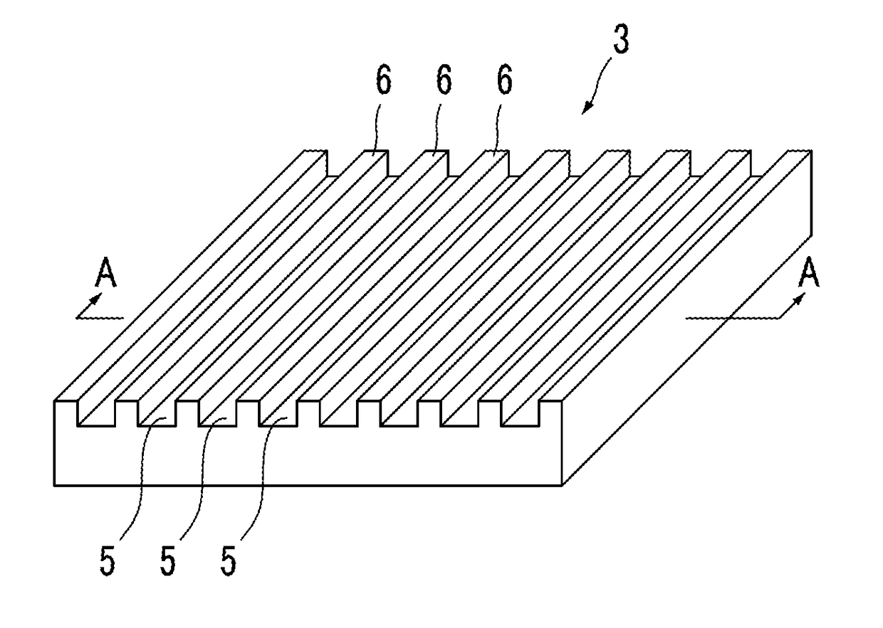
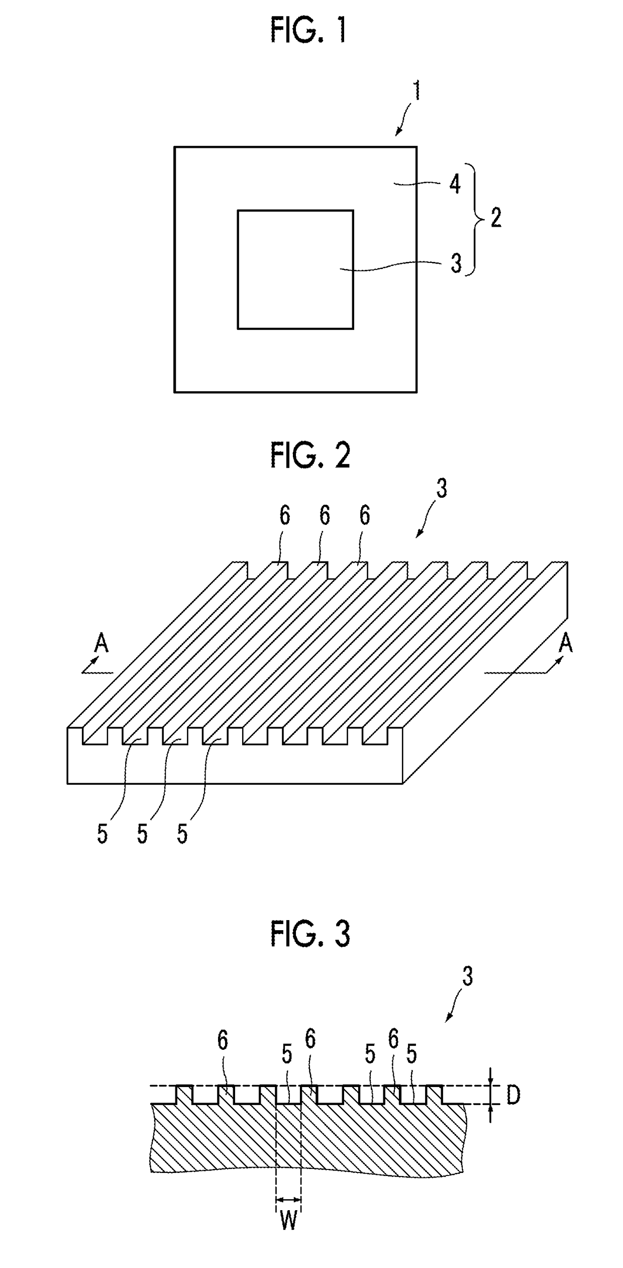
The present invention relates to a flexographic printing plate with improved ink transferability. The printing plate has a surface with a roughness structure consisting of a non-image area and an image area. The image area has an average roughness curve element length between 15 to 120 μm, an oil-retention volume between 2 to 180, and a load length ratio between 30% and 90%. This structure enhances ink transferability and allows for high ink density printing in solid portions. The invention also provides a method for manufacturing the flexographic printing plate and its precursor.

Problems solved by technology

In addition, as a result of conducting investigations on the printing plates described in JP2003-043672A and JP2008-068432A, it has been found that ink transferability cannot be sufficiently improved and ink density becomes low in the solid portion.

Method used


Image

  • Flexographic printing plate, flexographic printing plate precursor, and manufacturing methods therefor
  • Flexographic printing plate, flexographic printing plate precursor, and manufacturing methods therefor
  • Flexographic printing plate, flexographic printing plate precursor, and manufacturing methods therefor

Examples


example 1

[0255]

[0256]80 parts by mass of EPDM: MITSUI EPT1045 (ethylene-propylene-diene copolymer, ethylene content: 58% by mass, diene content: 5% by mass, kind of diene: (dicyclopentadiene (DCPD), manufactured by Mitsui Chemicals, Inc.) as a polymer 1, 12 parts by mass of carbon black #45L (nitrogen adsorption specific surface area: 125 m2 / g, DBP absorption: 45 cm3 / 100 g, manufactured by Mitsubishi Chemical Corporation) as a photothermal conversion agent, and 5 parts by mass of PERCUMYL D40 (dicumyl peroxide (40% by mass), manufactured by NOF CORPORATION) were kneaded to prepare a resin composition A.

[0257]

[0258]The obtained resin composition A was crosslinked by heating at a pressure of 10 MPa and 160° C. for 20 minutes using a heating press machine (MP-WCL, manufactured by Toyo Seiki Seisaku-sho, Ltd.) and thus a crosslinked relief forming layer having a thickness of 915 μm was formed.

[0259]A photocuring composition (3030, manufactured by Three Bond Co., Ltd.) was applied to one side of ...

examples 2 to 15

[0267]Flexographic printing plates were produced in the same manner as in Example 1 except that the conditions in laser engraving (light quantity and image pattern) were changed to the conditions shown in Table 1 below.

[0268]In Table 1 below, regarding the image patterns, the image patterns shown in FIGS. 6B to 6H are respectively denoted as image patterns 2 to 8.

[0269]In the image pattern 2 (FIG. 6B), the line width of the recessed line was 1 pixel (10 μm), the line width of the projecting line was 2 pixels (20 μm), and the pitch was 3 pixels.

[0270]In the image pattern 3 (FIG. 6C), the line width of the recessed line was 1 pixel (10 μm), the line width of the projecting line was 3 pixels (30 μm), and the pitch was 4 pixels.

[0271]In the image pattern 4 (FIG. 6D), the line width of the recessed line was 1 pixel (10 μm), the line width of the projecting line was 5 pixels (50 μm), and the pitch was 6 pixels.

[0272]In the image pattern 5 (FIG. 6E), the line width of the recessed line was...

examples 16 to 18

[0276]Flexographic printing plates were produced in the same manner as in Example 1 except that the polymer 1 used in the resin composition was changed to polymers 2 to 4 shown below, respectively, the amount of carbon black was changed to 9 parts by mass, the amount of PERCUMYL D40 was changed to 0.2 parts by mass, and the heating pressing was performed at 180° C. for 10 minutes.

Polymer 2: syndiotactic 1,2-polybutadiene RB820 (manufactured byJSR Corporation)Polymer 3: syndiotactic 1,2-polybutadiene RB830 (manufactured byJSR Corporation)Polymer 4: syndiotactic 1,2-polybutadiene RB840 (manufactured byJSR Corporation)


PUM

PropertyMeasurementUnit
roughnessaaaaaaaaaa
roughnessaaaaaaaaaa
surface average roughnessaaaaaaaaaa

Abstract

The present invention is to provide a flexographic printing plate having high ink transferability and making it possible to perform printing with a high ink density in a solid portion, a flexographic printing plate precursor, a method for manufacturing a flexographic printing plate, and a method for manufacturing a flexographic printing plate precursor. A flexographic printing plate includes a relief layer including a non-image area and an image area having an uneven structure formed on a surface thereof, in which an average length RSm of roughness curve elements of the surface of the image area having the uneven structure is 15 to 120 μm, an oil-retention volume A2 is 2 to 180, and a load length ratio Rmr 30% at a cutting level of 30% is 20% to 90%.

Description

CROSS-REFERENCE TO RELATED APPLICATIONS[0001]This application is a Continuation of PCT International Application No. PCT / JP2016 / 086744 filed on Dec. 9, 2016, which claims priority under 35 U.S.C. § 119(a) to Japanese Patent Application No. 2016-000087 filed on Jan. 4, 2016. The above application is hereby expressly incorporated by reference, in its entirety, into the present application.BACKGROUND OF THE INVENTION1. Field of the Invention[0002]The present invention relates to a flexographic printing plate, a flexographic printing plate precursor, a method for manufacturing a flexographic printing plate, and a method for manufacturing a flexographic printing plate precursor.2. Description of the Related Art[0003]A flexographic printing plate having a flexible relief layer made of resin or rubber has a relatively soft projecting portion (image area) for printing and can conform to various shapes. Therefore, a flexographic printing plate is used for printing performed on objects to be ...

Claims


Application Information

Patent Timeline
Patent Type & Authority Applications(United States)
IPC IPC(8): B41N1/06B41C1/05G03F7/039
CPCB41N1/06B41C1/05G03F7/039B41N1/12G03F7/202
Inventor SATO, HIROSHIMORIKAWA, SEIICHIRO
Owner FUJIFILM CORP
Learn More