Vehicle propulsion system and method for a vehicle

a technology for propulsion systems and vehicles, applied in the direction of clutches, gearing elements, gearing, etc., can solve the problems of increased requirements, increased requirements, and increased requirements, so as to reduce the number of engine speed profiles, reduce the effect of engine speed profiles that are reduced during the engine stop or start process and increase the requiremen

Active Publication Date: 2018-11-08
GM GLOBAL TECH OPERATIONS LLC
View PDF0 Cites 0 Cited by
  • Summary
  • Abstract
  • Description
  • Claims
  • Application Information

AI Technical Summary

Benefits of technology

[0014]In this manner, a signal generated by a crankshaft sensor may be reliably used to coordinate application of a transmission clutch to eliminate and/or reduce pulses in an engine speed profile as the engine transitions between an operating speed and a full stop, whether it is during an engine stop process or engine start process, without limitation.
[0015]Further, even in a hybrid type of vehicle propulsion system that may have one or more electric motors which may be used to adjust the engine speed profile during an engine stop or start process, use of a transmission clutch may further supplement the ability of the electric motor to control the engine speed profile. This may be especially helpful in a mild-hybrid type of vehicle propulsion system which may include an electric motor having a reduced capacity in comparison to a strong hybrid which may have a more powerful motor. The assistance of the clutch in removing or eliminating pulses in the engine speed profile may enable the use of a smaller electric motor and battery.
[0016]Further, reduction of pulses in an engine speed profile during a

Problems solved by technology

This compression and expansion results in accelerations, variances, bumpiness or “jerkiness” in the profile of the engine speed as the engine slows from idle speed to being fully stopped.
In other words, the engine speed p

Method used


Image

  • Vehicle propulsion system and method for a vehicle
  • Vehicle propulsion system and method for a vehicle
  • Vehicle propulsion system and method for a vehicle

Examples


Embodiment Construction

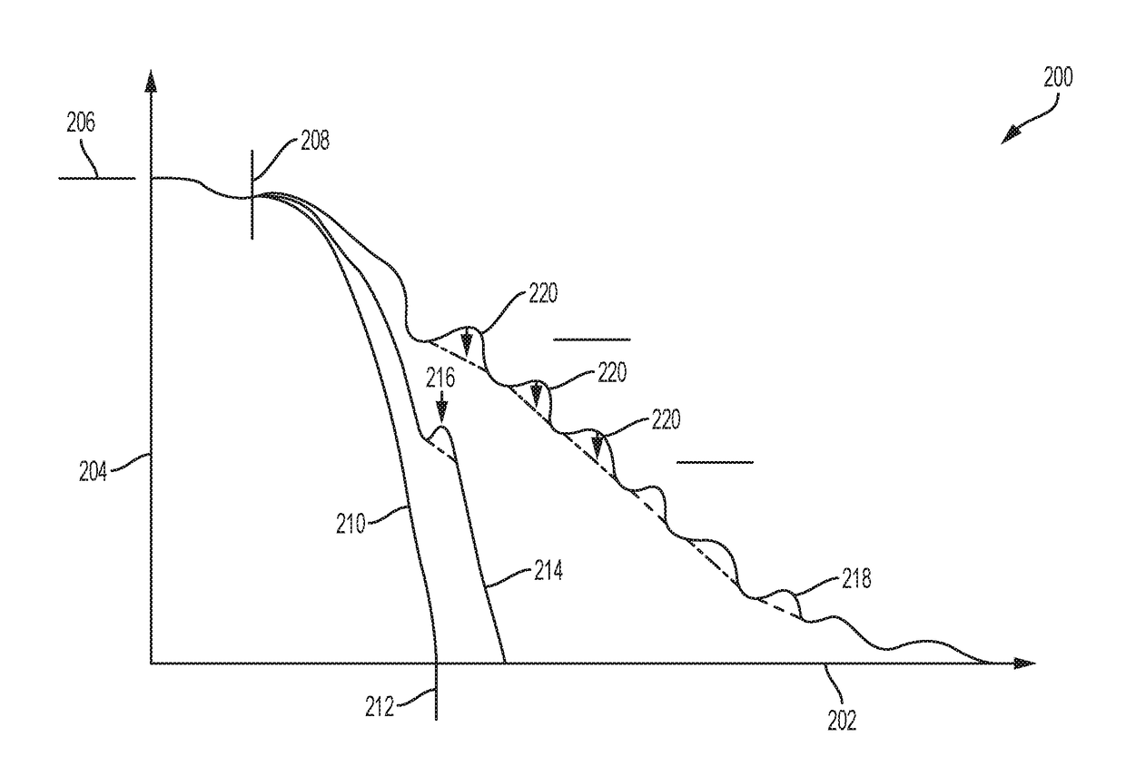
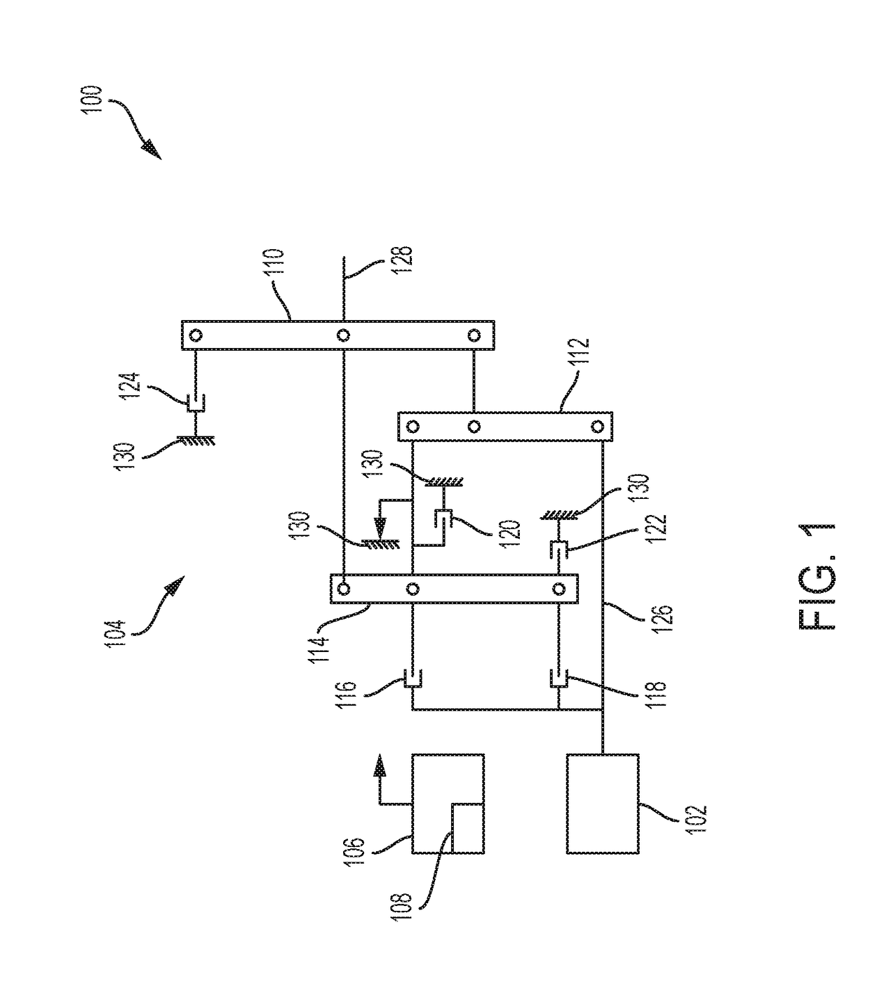
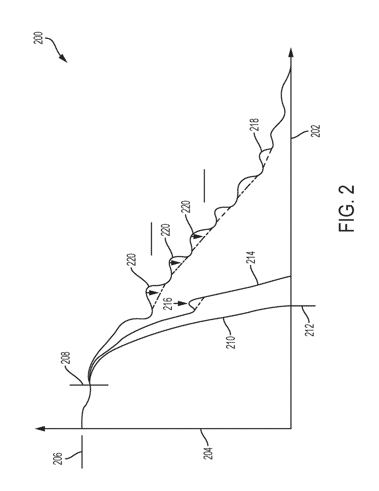
[0025]FIG. 1 is a schematic lever diagram of an exemplary vehicle propulsion system 100 in accordance with the present invention. The system 100 includes an engine 102 and a transmission 104. A controller 106 executes an exemplary method 108 to mitigate pulses in the engine speed profile during an engine stop or start process. The controller 106 mitigates the pulses by controlling the actuation of one or more clutches in the transmission 104. While FIG. 1 illustrates a six speed automatic transmission as an exemplary embodiment, the propulsion system 100 may include any type of transmission such as, for example, a dual clutch transmission, or any other type of automatic transmission having any number of available gear ratios which includes a controllable clutch that is capable of slowing the engine speed when engaged without limitation.

[0026]The transmission 104 includes a first planetary gear set 110, a second planetary gear set 112, and a third planetary gear set 114. The transmis...


PUM


Abstract

A vehicle propulsion system includes an engine including a crankshaft and adapted to generate torque, a crankshaft sensor that outputs a signal that is indicative of a rotary position of the crankshaft, a transmission with a clutch that is connected to the engine to receive the torque from the engine, a drive member connected to the transmission to receive torque from the transmission, and a controller that commands operation of the clutch based upon the signal from the crankshaft sensor for controlling engine compression pulse disturbances as the engine speed changes from an elevated rpm to low or zero rpm as well as low or zero rpm to an elevated rpm.

Description

FIELD[0001]The present disclosure relates to vehicle propulsion system and method for a vehicle.INTRODUCTION[0002]This introduction generally presents the context of the disclosure. Work of the presently named inventors, to the extent it is described in this introduction, as well as aspects of the description that may not otherwise qualify as prior art at the time of filing, are neither expressly nor impliedly admitted as prior art against this disclosure.[0003]In order to minimize idle fuel consumption, some vehicle propulsion systems selectively cut off the supply of fuel and spark to an internal combustion engine when the vehicle would otherwise be idling. As the engine speed is reduced during an engine stop process, in a four stroke engine each cylinder tends to capture and compress a volume of air during the compression stroke. Following the compression stroke as the piston reverses direction after reaching top dead center in the cylinder, the trapped volume of higher pressure ...

Claims


Application Information

Patent Timeline
IPC IPC(8): F16H61/14B60W10/02
CPCB60W30/18027B60W10/11B60W2510/0638B60W2710/021B60W30/181Y10T477/6437Y10T477/78B60W30/18018F16D2500/3067Y10T477/753F16H61/143B60W10/02F16D2500/3041F16D2500/30408F16D2500/3026F16D2500/30402F16D2500/30406B60W2510/0685F16D48/06F16D2500/70442F16D2500/50293F16D2500/504F16D2500/5122F16D2500/306F16D2500/1062F16D2500/10412F16D2500/1045F16D2500/1026F16H63/46F16H2312/14
Inventor SIME, KARL A.DLUGOSS, RANDALL B.
Owner GM GLOBAL TECH OPERATIONS LLC
Why Eureka
Try Eureka