Power supply apparatus and image forming apparatus

a technology of power supply apparatus and image forming apparatus, which is applied in the direction of process and machine control, corona discharge, instruments, etc., can solve the problems of high oscillation frequency, complicated control, and frequent radiation noise, so as to reduce noise, reduce oscillation frequency, and reduce output voltage variations

Active Publication Date: 2018-11-22
CANON KK
View PDF6 Cites 5 Cited by
  • Summary
  • Abstract
  • Description
  • Claims
  • Application Information

AI Technical Summary

Benefits of technology

[0005]One embodiment of the present invention is a power supply apparatus and an image forming apparatus, which are capable of reducing variations in output voltage due to variations in components while decreasing an oscillation frequency and reducing noise with use of a simple and low-cost circuit configuration.

Problems solved by technology

However, the related-art circuit has problems in that the control is complicated, an oscillation frequency is high, and radiation noise frequently occurs.
Therefore, it is difficult to directly control the output voltage by a CPU, and, for example, as disclosed in Japanese Patent No. 5627607, a voltage-controlled oscillator (VCO) or a dedicated IC is used.

Method used


Image

  • Power supply apparatus and image forming apparatus
  • Power supply apparatus and image forming apparatus
  • Power supply apparatus and image forming apparatus

Examples


first embodiment

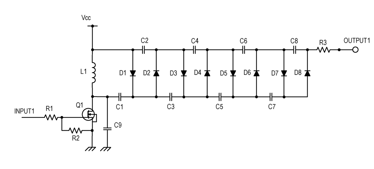
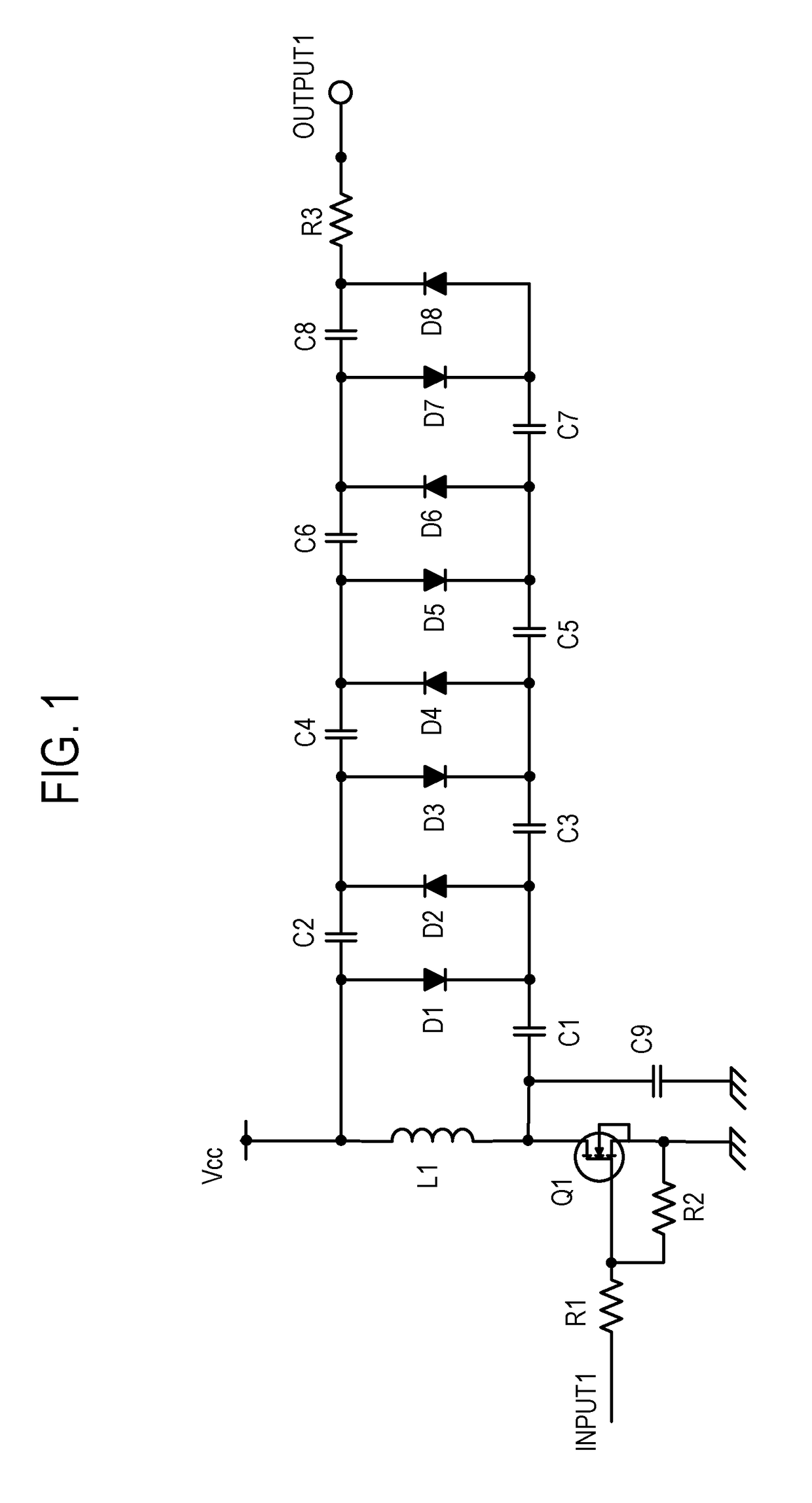
[0017]FIG. 1 is a circuit diagram of a power supply apparatus according to the present invention. A circuit illustrated in FIG. 1 is a multistage rectification circuit, and is configured to boost a voltage by repeatedly charging capacitors and adding the voltages. The multistage rectification circuit includes a resistor R1 to a resistor R3, a coil L1, a MOSFET (hereinafter referred to as “FET”) Q1, which is a type of field-effect transistor, a capacitor C1 to a capacitor C9, and a diode D1 to a diode D8. A transistor may be used as Q1. Further, “Vcc” represents a DC voltage, which is, for example, 24 V.

[0018]In the power supply apparatus of FIG. 1, the FET Q1 serving as a switching element is turned on or off in accordance with a pulse signal input to a gate terminal thereof, to thereby drive the coil L1. Further, the diode D1 and the capacitor C1, the diode D2 and the capacitor C2, and other combinations of the diodes and the capacitors each function as a rectification unit. The mu...

second embodiment

[0046]Further, when the halt period of the case in which the operation is regarded as the intermittent oscillation operation is decreased too much, there arises a problem in that the variations in output voltage are increased again. This state is described as the present invention with reference to FIG. 5. FIG. 5 is a graph for showing the waveform of the pulse signal input to the input 1 and the waveform of the current Li. The horizontal axis indicates time, and there is shown an example of a case in which four pulse signals are successively input at short intervals. The waveform of the current Li after the fourth pulse signal is input in the oscillation period and the FET Q1 is turned on is converged while performing free oscillation.

[0047]In this case, it is assumed that, at a time point of “Y” in FIG. 5, the first input in the oscillation period of the next cycle is performed. The first pulse signal in the next cycle at this time is indicated by the broken line, and a period fro...

third embodiment

[0051]A laser beam printer is described as an example of the image forming apparatus according to the present invention. In FIG. 6, a schematic configuration of the laser beam printer as an example of an electrophotographic printer is illustrated. A laser beam printer 300 includes a photosensitive drum 311 serving as an image bearing member on which an electrostatic latent image is to be formed, a charging unit 317 (charging device) configured to uniformly charge the photosensitive drum 311, and a developing unit 312 (developing device) configured to develop the electrostatic latent image formed on the photosensitive drum 311 with toner. A toner image developed on the photosensitive drum 311 is transferred by a transfer unit 318 (transfer device) onto a sheet (not shown) serving as a recording material supplied from a cassette 316. The toner image transferred onto the sheet is fixed by a fixing device 314 and is discharged to a tray 315. The photosensitive drum 311, the charging uni...


PUM


Abstract

The power supply apparatus includes an inductor; a switching element, which is connected in series to the inductor, and is configured to be driven in accordance with an input pulse signal; and a booster circuit, which is connected to both ends of the inductor, and includes a plurality of rectification units each including a diode and a capacitor, wherein the power supply apparatus is configured to repeat an operation of successively driving the switching element in accordance with the input pulse signal in a cycle that is longer than a cycle in which the switching element is successively driven.

Description

BACKGROUND OF THE INVENTIONField of the Invention[0001]The present invention relates to a power supply apparatus, for example, a high-voltage power supply configured to generate a high voltage, and an image forming apparatus including the power supply apparatus.Description of the Related Art[0002]Hitherto, there are various products that handle a high voltage. Examples thereof include air cleaners, air conditioners, ionizers, cathode ray tube televisions, laser printers, and particle accelerators. In many cases, a high voltage is generated by boosting a low voltage, and there are several types of circuits for generating the high voltage. Among the several types of circuits, a circuit called Cockcroft-Walton circuit is often employed. In the Cockcroft-Walton circuit, capacitors and diodes are connected to one another in a ladder-like manner to repeatedly perform charge / discharge and addition of voltages, to thereby boost the voltage. The Cockcroft-Walton circuit can be achieved with ...

Claims


Application Information

Patent Timeline
Patent Type & Authority Applications(United States)
IPC IPC(8): G03G15/02H02M3/156G03G15/00H04N1/00
CPCG03G15/0283H02M3/156G03G15/80H04N1/00885H02M3/155H02M7/10H02M1/007
Inventor HIRABAYASHI, JUN
Owner CANON KK
Why Eureka
Try Eureka