
Composition for encapsulating organic light emitting element and organic light emitting element display device manufactured therefrom

Active Publication Date: 2018-11-29
SAMSUNG SDI CO LTD
View PDF0 Cites 4 Cited by
  • Summary
  • Abstract
  • Description
  • Claims
  • Application Information

AI Technical Summary

Benefits of technology

The present invention provides a composition for encapsulation of an organic light emitting device that has good plasma resistance and low modulus. It can be used in flexible displays and has a high photocuring rate. The composition can easily form an organic barrier layer and has high light transmittance.

Problems solved by technology

Such an organic light emitting device can suffer from deterioration in light emitting properties upon contact with external moisture and / or oxygen.
When the organic barrier layer is etched, an encapsulation function of the organic barrier layer can be damaged.
As a result, the organic light emitting device can suffer from deterioration in light emitting properties and reliability.

Method used


Image

  • Composition for encapsulating organic light emitting element and organic light emitting element display device manufactured therefrom
  • Composition for encapsulating organic light emitting element and organic light emitting element display device manufactured therefrom
  • Composition for encapsulating organic light emitting element and organic light emitting element display device manufactured therefrom

Examples


example 2

Preparative Example 2

[0118]A monomer represented by Formula 9 was obtained in the same manner as in Preparative Example 1 except that 25 g of 3-phenyl-1,1,3,5,5-pentamethyltrisiloxane (Gelest Inc.) was used instead of 21 g of 3,3-diphenyl-1,1,5,5-tetramethyltrisiloxane.

example 3

Preparative Example 3

[0119]In a 1,000 ml flask provided with a cooling tube and a stirrer, 300 ml of ethyl acetate, 25 g of 3-phenyl-1,1,1,3,5,5-hexamethyltrisiloxane (Gelest Inc.) and 47 g of allyl alcohol were placed, followed by nitrogen purging for 30 minutes. Next, 72 ppm of Pt-on-carbon black powder (Aldrich GmbH) was added thereto, followed by heating the flask to 80° C. and stirring the components for 4 hours. The remaining solvent was removed by distillation, thereby obtaining a compound. 65.5 g of the obtained compound and 48 g of triethylamine were sequentially added to 300 ml of dichloromethane, followed by slowly adding 31.3 g of methacryloyl chloride while stirring the mixture at 0° C. The remaining solvent was removed by distillation, thereby obtaining a monomer represented by Formula 13 and having a purity of 97% as determined by HPLC (molecular weight: 410.73 g / mol). (1H NMR: 67.61, m, 3H: δ7.12, m, 2H: δ6.25, d, 1H: δ6.02, dd, 1H: δ3.87, m, 2H: δ2.82, s, 3H: δ1.54,...

example 4

Preparative Example 4

[0120]A monomer represented by Formula 14 and having a purity of 96% as determined by HPLC (molecular weight: 410.73 g / mol) was obtained in the same manner as in Preparative Example 3 except that 25 g of 3-phenyl-1,1,1,5,5,5-hexamethyltrisiloxane (Gelest Inc.) was used instead of 25 g of 3-phenyl-1,1,1,3,5,5-hexamethyltrisiloxane (Gelest Inc.). (1H NMR: 67.61, m, 3H: δ7.12, m, 2H; 56.25, d, 1H: δ6.02, dd, 1H: δ3.87, m, 2H: δ2.82, s, 3H δ1.54, m, 2H: δ0.58, m, 2H: δ0.02, m, 18H).

[0121]Details of components used in Examples and Comparative Examples were as follows.

[0122](A) Non-silicone-based photocurable polyfunctional monomer: (A1) 1,12-dodecanediol dimethacrylate (Sartomer Co., Ltd.), (A2) 1,6-hexanediol dimethacrylate (Sartomer Co., Ltd.)

[0123](B) Silicone-based photocurable polyfunctional monomer: (B1) monomer of Preparative Example 1, (B2) monomer of Preparative Example 2

[0124](C) Non-silicone-based photocurable monofunctional monomer: 2-phenylphenoxyethyl a...


PUM

PropertyMeasurementUnit
Fractionaaaaaaaaaa
Fractionaaaaaaaaaa
Pressureaaaaaaaaaa

Abstract

Provided are a composition for encapsulating an organic light emitting element and an organic light emitting element display device manufactured therefrom, the composition comprising: (A) a non-silicone-based photocurable multifunctional monomer; (B) a silicone-based photocurable multifunctional monomer; (C) a non-silicone-based photocurable monofunctional monomer; (D) a silicone-based photocurable monofunctional monomer; and (E) an initiator, wherein the silicone-based photocurable multifunctional monomer (B) is represented by chemical formula 1.

Description

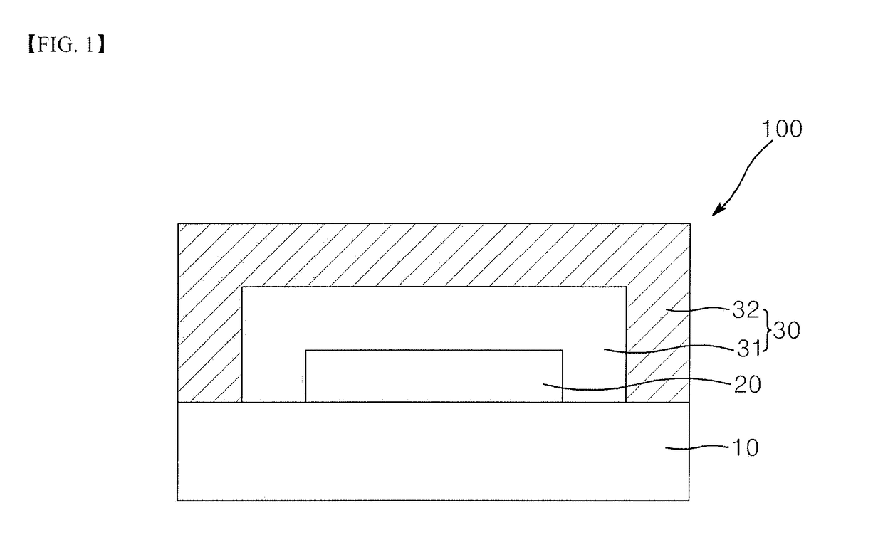
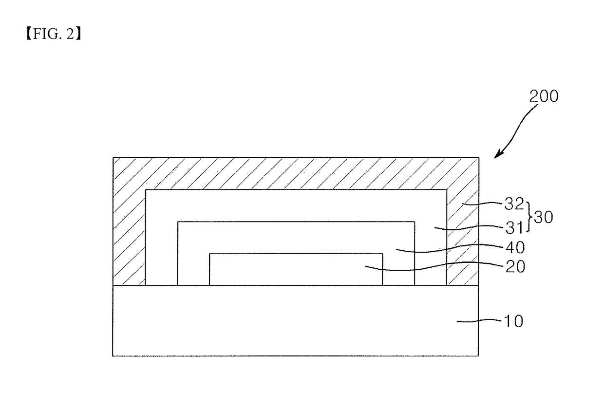
TECHNICAL FIELD[0001]The present invention relates to a composition for encapsulation of an organic light emitting device and an organic light emitting display fabricated using the same.BACKGROUND ART[0002]An organic light emitting display includes an organic light emitting device. Such an organic light emitting device can suffer from deterioration in light emitting properties upon contact with external moisture and / or oxygen. Thus, the organic light emitting device must be encapsulated with an encapsulation composition. The organic light emitting device is encapsulated in a multilayer structure including an inorganic barrier layer and an organic barrier layer. The inorganic barrier layer is formed by plasma deposition, which can cause the organic barrier layer to be etched by plasma. When the organic barrier layer is etched, an encapsulation function of the organic barrier layer can be damaged. As a result, the organic light emitting device can suffer from deterioration in light em...

Claims


Application Information

Patent Timeline
IPC IPC(8): H01L51/00H01L33/00C07F7/18C08F22/12
CPCC08F22/12C07F7/1804H01L51/00H01L33/00C08F2/50C08F230/08C08G77/20C08F220/301H10K50/844Y02E10/549C08F222/102H10K99/00
Inventor NAM, SEONG RYONGCHOI, MI JEONGKO, SUNG MIN
Owner SAMSUNG SDI CO LTD
Learn More