Charging facility and energy management method for charging facility

a charging facility and energy management technology, applied in charging stations, electric vehicle charging technology, transportation and packaging, etc., to achieve the effect of simple configuration and flexible operation of the entire charging facility

a charging facility and energy management technology, applied in charging stations, electric vehicle charging technology, transportation and packaging, etc., to achieve the effect of simple configuration and flexible operation of the entire charging facility

US20180361859A1Active Publication Date: 2018-12-20MITSUBISHI HEAVY IND LTD

Image

  • Charging facility and energy management method for charging facility
  • Charging facility and energy management method for charging facility
  • Charging facility and energy management method for charging facility

Examples


embodiment

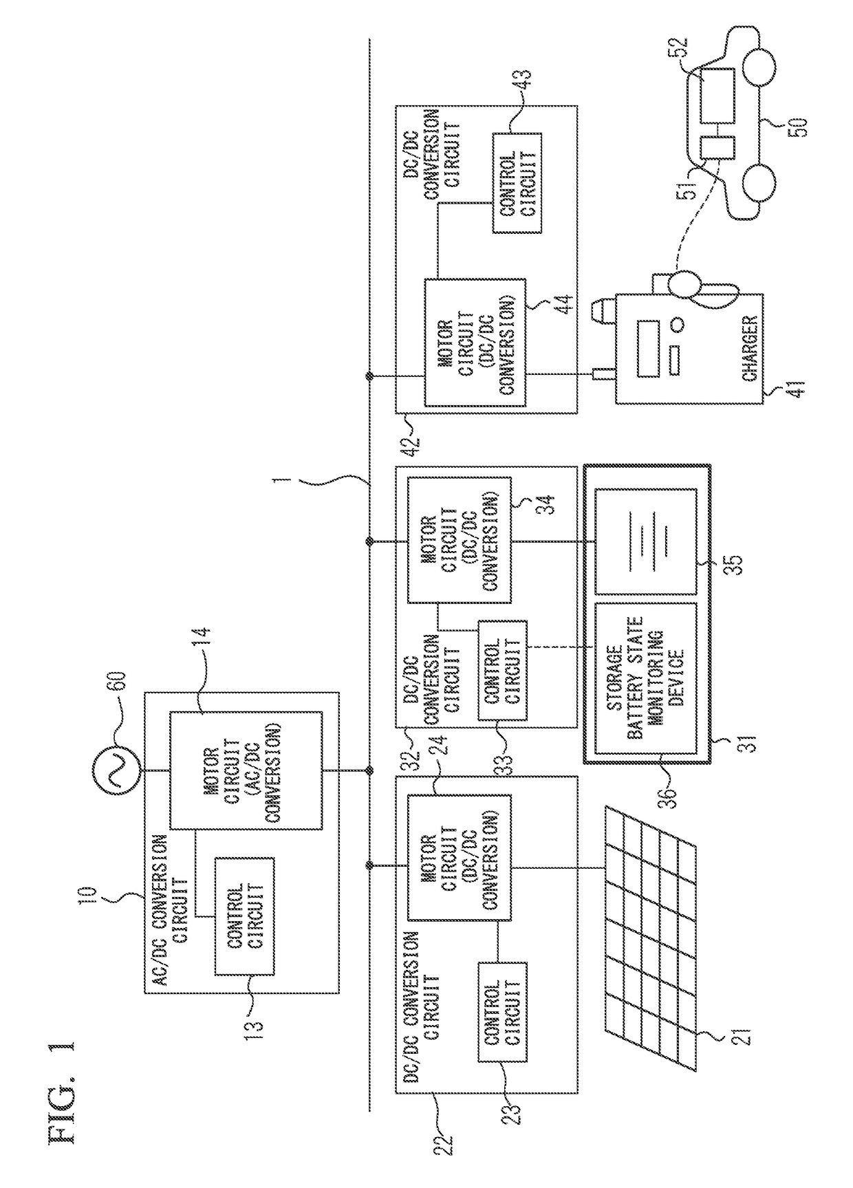
[0017]In an embodiment of the invention, one configuration example of a charging facility in which a plurality of power converters are connected to a DC bus will be described.

[0018]Each of a plurality of power converters can be broadly classified into three types. The power converters included in the first classification convert AC power supplied from the outside, such as a system power supply, to DC power and supply the DC power to the DC bus. The power converter included in the second classification supply power generated by a power generation device, such as a solar power generation module, to the DC bus. The power converters included in the third classification receive power from the DC bus to charge the storage device. The power converters included in the third classification also discharge power charged in the storage device and supply power to the DC bus.

[0019]The charging facility described herein is connected to a system power supply, and has one power generation device and...


PUM


Abstract

A charging facility collects DC power supplied from a plurality of power supply devices in a DC bus, and then uses the DC power to charge an on-board rechargeable battery for an electric vehicle. In an energy management method for a charging facility, each power supply device operates under independent automatic control according to a change in voltage in the DC bus. An upper-level control unit which collectively controls a plurality of power supply sources is not required, and a plurality of power supply devices can be combined with a simple configuration achieved by merely connecting respective output terminals to the DC bus. In addition, the entire charging facility can be operated flexibly. Thus, it is possible to achieve a simple configuration and to allow flexible operation while a plurality of power converters are combined with a system power supply.

Description

RELATED APPLICATIONS[0001]The present application is a continuation of U.S. application Ser. No. 14 / 917,948 filed Mar. 10, 2016, which is a National Phase of PCT / JP2014 / 074572 filed Sep. 17, 2014, and claims priority based on Japanese Patent Application No. 2013-194491 filed on Sep. 19, 2013.TECHNICAL FIELD[0002]The present invention relates to a fast charging facility for an electric vehicle linked with a power generation device, such as a solar power generation module, or a charging / discharging device, such as a fixed storage battery, and can be suitably applied to an energy management method for each device associated with the charging facility.BACKGROUND ART[0003]At the time of fast charging of an electric vehicle, power which is consumed at the time of traveling of the electric vehicle should be supplied in a comparatively short charging time. In other words, a large load is applied to a so-called system power supply, that is, a power facility which supplies commercial power, i...

Claims


Application Information

Patent Timeline
20 Dec 2018
Publication
US20180361859A1
IPC
B60L11/18; H02J7/34; H02J3/38; H02J7/00; H02J7/02; H02K47/14; H02J3/32; H02J7/35
CPC
H02J7/34; Y02E10/566; Y02E10/563; H02J3/383; H02J3/32; H02J7/0068; H02J7/022; H02J3/386
Inventors
YOKO, RYOSUKE; MARUYAMA, MASANORI