Charging system for electric vehicles

a charging system and electric vehicle technology, applied in the direction of secondary cell service/maintenance, electrochemical generators, battery/cell propulsion, etc., can solve the problems of high heat generation, inability to provide charging speeds for electric vehicles, and inability to adequately dissipate heat, so as to effectively dissipate heat loss and exclude overheating of charging cables

Active Publication Date: 2018-12-27
DR ING H C F PORSCHE AG
View PDF9 Cites 8 Cited by
  • Summary
  • Abstract
  • Description
  • Claims
  • Application Information

AI Technical Summary

Benefits of technology

[0016]In particular, an electrical energy storage device makes it possible to provide a charging power of more than 300 kW for each vehicle. High charging speeds can therefore be achieved.
[0028]According to one advantageous development, the power electronics and the, or each, electrical energy storage device and the charging cable of the, or each, charging station can be cooled with the aid of the re-cooling apparatus. The cooling of the charging cables of the charging stations is important, in particular, in order to effectively dissipate the heat loss arising in the case of high charging powers or charging speeds and to exclude overheating of the charging cables.

Problems solved by technology

The DC charging mode can be used to achieve higher charging speeds than the AC charging mode, but it has hitherto not yet been possible to provide charging speeds for the traction battery of an electric vehicle in the DC charging mode which are of the order of magnitude of a refueling operation in conventional vehicles driven by internal combustion engines.
Previously known charging systems for electric vehicles which are used for the DC charging of the traction battery of electric vehicles have accordingly not been able to hitherto ensure high charging speeds since, on the one hand, the electrical network power provided by the available electrical current and voltage supply network is not sufficient under certain circumstances to provide a desired charging speed and, on the other hand, taking into account the fact that, at high charging speeds, high losses also occur and result in a high development of heat which has hitherto not been able to be sufficiently dissipated, however.

Method used


Image

  • Charging system for electric vehicles
  • Charging system for electric vehicles
  • Charging system for electric vehicles

Examples


Embodiment Construction

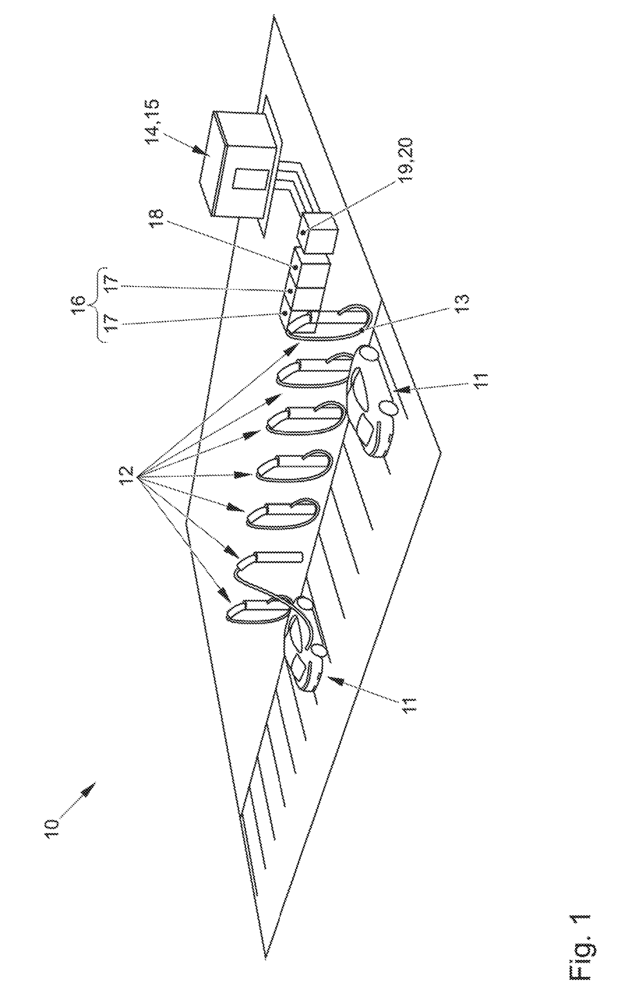
[0035]FIG. 1 shows, in a highly schematic manner, the basic structure of a charging system 10 according to aspects of the invention for electric vehicles 11. The charging system 10 has a plurality of charging stations 12 for electric vehicles, an electric vehicle 11 being able to be respectively charged in the region of each of these charging stations 12, which are also referred to as charging poles, specifically by coupling the traction battery of the electric vehicle 11 to the charging station 12 via a charging cable 13 of the respective charging station 12.

[0036]FIG. 1 shows two electric vehicles 11 which are connected to the respective charging station 12 via a charging cable 13.

[0037]The charging system 10 can be supplied with electrical voltage or electrical current from an electrical current and voltage supply network 14, a transformer 15 of which is shown. In this case, the electrical current and voltage supply network 14 is characterized by a defined electrical network powe...


PUM

PropertyMeasurementUnit
charging poweraaaaaaaaaa
electrical currentaaaaaaaaaa
charging speedaaaaaaaaaa

Abstract

Charging system for electric vehicles, having: a charging station to which a traction battery of an electric vehicle can be coupled via a charging cable; power electronics, the charging station being able to be connected, with the interposition of the power electronics, to an electrical current and voltage supply network which provides a defined electrical network power; an electrical storage device which is connected between the electrical current and voltage supply network and the charging station such that said storage device is charged on the basis of the electrical network power and is discharged on the basis of a charging speed of the charging station; a re-cooling apparatus, the charging station, the power electronics and the electrical storage device connected to the re-cooling apparatus which provides a defined as thermal re-cooling power; a thermal storage device connected to the re-cooling apparatus, to the charging station, to the power electronics and to the electrical storage device such that said storage device or a cooling medium of said storage device is heated on the basis of the power loss of the power electronics, charging station and electrical storage device and can be cooled on the basis of the thermal re-cooling power of the re-cooling apparatus.

Description

CROSS-REFERENCE TO RELATED APPLICATION[0001]This application claims priority to German Patent Application No. DE 10 2017 113 842.0, filed Jun. 22, 2017, which is incorporated by reference herein in its entirety.FIELD OF THE INVENTION[0002]The present invention relates to a charging system for electric vehicles.BACKGROUND OF THE INVENTION[0003]The so-called AC charging mode and the so-called DC charging mode are known for charging an electric vehicle, specifically for charging a traction battery of an electric vehicle.[0004]In the AC charging mode, the electric vehicle is connected, via its on-board charging device, to an electrical current and voltage supply network which provides AC voltage and alternating current, the on-board charging device carrying out the conversion to direct current. In the so-called AC charging mode, the charging speed for the traction battery is restricted. Charging times in the AC charging mode are several hours for each 100 kilometer range.[0005]The tract...

Claims


Application Information

Patent Timeline
Patent Type & Authority Applications(United States)
IPC IPC(8): B60L11/18H02J7/04H01M10/613H01M10/44
CPCB60L11/1824H02J7/04H01M10/613H01M10/443B60L53/302B60L53/53B60L53/62H01M10/66B60L53/14B60L53/67Y02T90/16Y02T10/70Y02T10/7072Y02T90/14Y02T90/12Y02E60/10B60L50/50B60S5/00H02J7/02B60L53/30
Inventor GOTZ, STEFANGROMANUEL
Owner DR ING H C F PORSCHE AG
Why Eureka
Try Eureka