Methods and system for diagnosing a particulate filter sensor

a technology of filter sensor and particulate filter, which is applied in the direction of electrical control, machines/engines, output power, etc., can solve the problems of difficult to determine whether or not the differential pressure sensor is providing reliable information, and achieve the effect of less particulate matter, less power, and more efficiency

Active Publication Date: 2019-01-17
FORD GLOBAL TECH LLC
View PDF5 Cites 15 Cited by
  • Summary
  • Abstract
  • Description
  • Claims
  • Application Information

AI Technical Summary

Benefits of technology

[0002]A gasoline or petrol spark ignited engine may include direct fuel injection. Fuel may be directly injected into an engine cylinder so that evaporation of the injected fuel may cool a charge in the engine cylinder. By cooling the cylinder charge, the engine may be operated at higher loads before engine knock occurs as compared to a port fuel injected engine. As such, the engine may operate more efficiently and may provide more power than a port fuel injected engine. However, directly injecting fuel into a cylinder may also provide an opportunity for injected fuel to stratify within an engine cylinder leading to carbonaceous exhaust. The carbonaceous exhaust may be stored in a particulate filter where it may be subsequently oxidized so that less particulate matter may be exhausted to atmosphere. Over time, the particulate filter may fill with carbonaceous soot such that the particulate filter may need to be regenerated. One way to determine whether or not the particulate filter is storing more than a threshold amount of carbonaceous soot is to measure a pressure change or pressure differential across the particulate filter. If the particulate filter is loaded with carbonaceous soot, a higher pressure differential may be indicated when engine air flow is high. However, it may be possible for a hose of a differential pressure sensor to detach from its anchored position due to maintenance or unforeseen circumstance. If the differential pressure sensor's hose becomes detached, it may be difficult to determine whether or not the differential pressure sensor is providing reliable information. Therefore, it may be desirable to provide a way of ascertaining whether or not differential pressure sensor data is reliable.

Problems solved by technology

However, directly injecting fuel into a cylinder may also provide an opportunity for injected fuel to stratify within an engine cylinder leading to carbonaceous exhaust.
However, it may be possible for a hose of a differential pressure sensor to detach from its anchored position due to maintenance or unforeseen circumstance.
If the differential pressure sensor's hose becomes detached, it may be difficult to determine whether or not the differential pressure sensor is providing reliable information.

Method used


Image

  • Methods and system for diagnosing a particulate filter sensor
  • Methods and system for diagnosing a particulate filter sensor
  • Methods and system for diagnosing a particulate filter sensor

Examples


Embodiment Construction

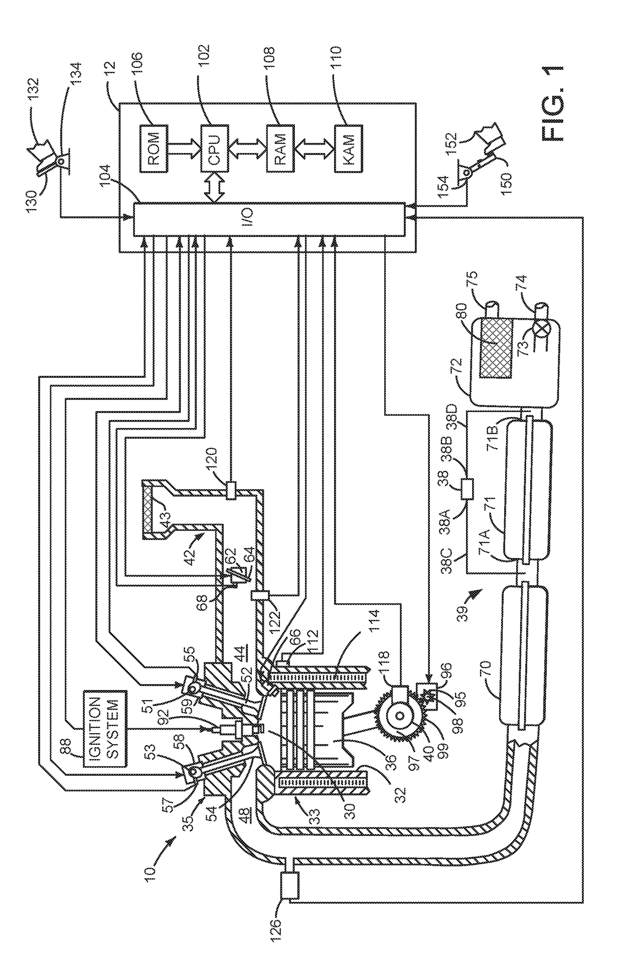
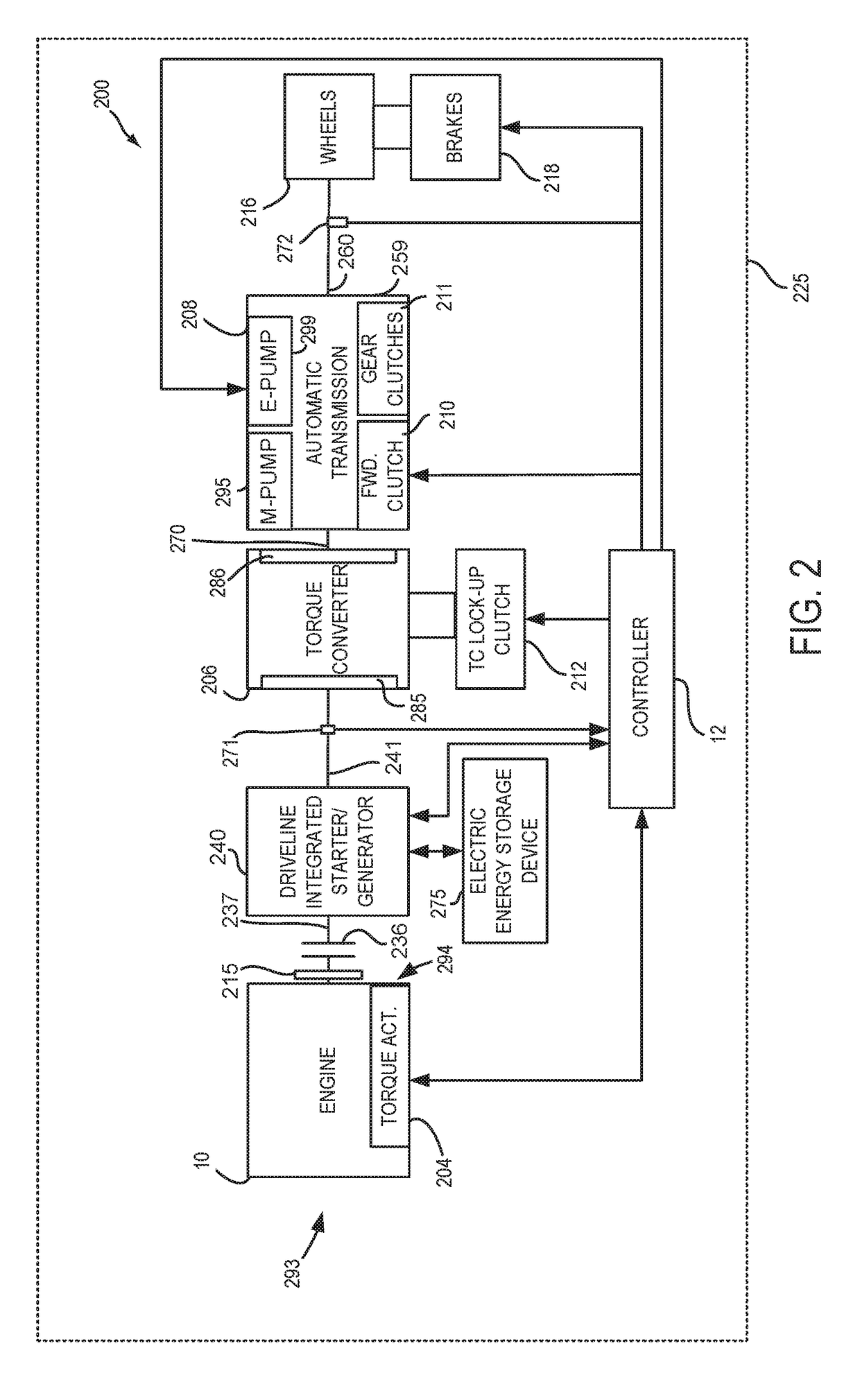
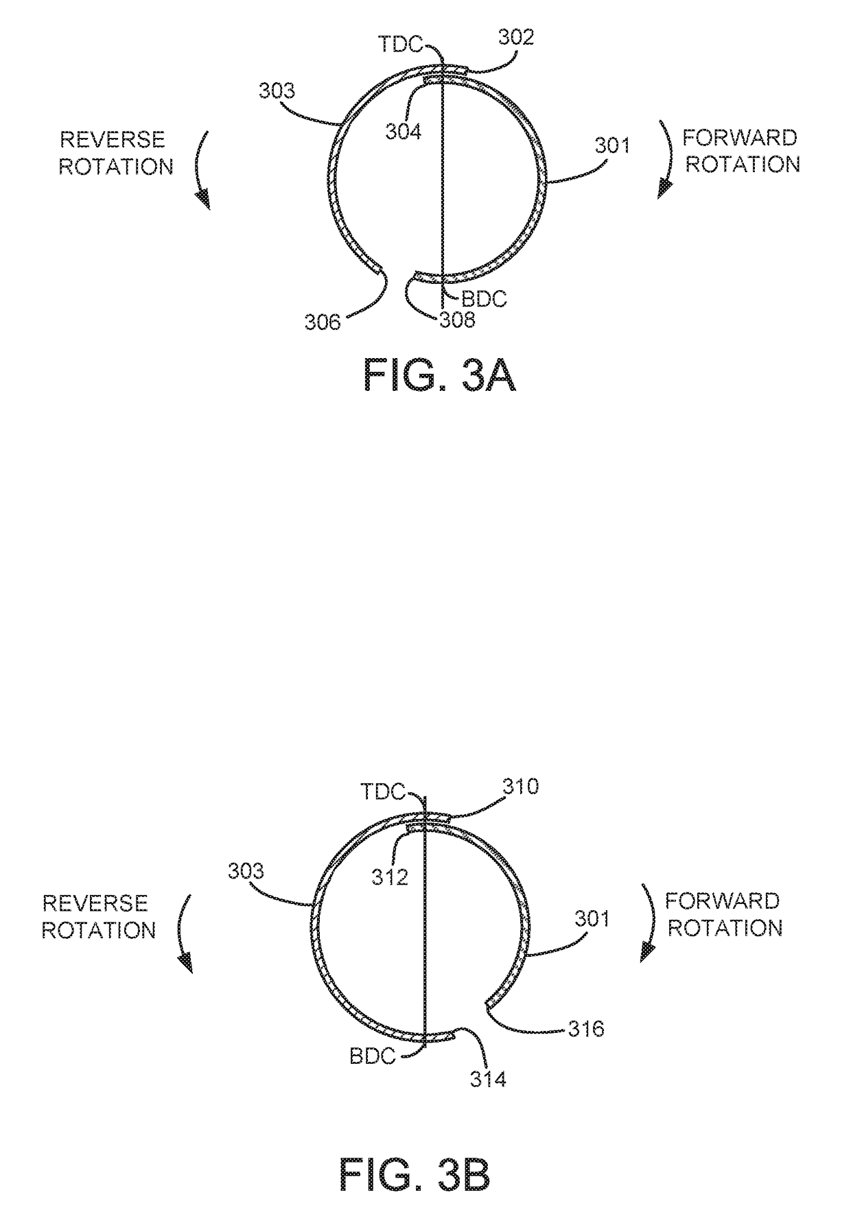
[0014]The present description is related to diagnosing operation of a differential pressure sensor that senses pressure on opposite sides of a particulate filter. The particulate filter may be incorporated into a vehicle with a spark ignited engine as is shown in FIG. 1. The engine may be part of a hybrid vehicle as shown in FIG. 2. The engine may also have intake and exhaust valve timing that provides for higher flow through the engine when the engine is rotated in a reverse direction as illustrated in FIGS. 3A and 3B. The vehicle may operate as shown in FIG. 4 according to the method of FIGS. 5A-5C.

[0015]Referring to FIG. 1, internal combustion engine 10, comprising a plurality of cylinders, one cylinder of which is shown in FIG. 1, is controlled by electronic engine controller 12. Engine 10 is comprised of cylinder head 35 and block 33, which include combustion chamber 30 and cylinder walls 32. Piston 36 is positioned therein and reciprocates via a connection to crankshaft 40. Fl...


PUM


Abstract

Systems and methods for diagnosing operation of a sensor of an exhaust system are presented. In one example, the systems and methods may diagnose operation of the sensor when an engine is combusting air and fuel. Further, operation of the sensor may be diagnosed when the engine is not combusting air and fuel so that vehicle occupants may not be disturbed by the diagnostic.

Description

FIELD[0001]The present description relates to methods and a system for determining the presence or absence of degradation of a differential pressure sensor that senses a pressure change across a gasoline particulate filter. The methods and systems may be particularly useful for direct fuel injection engines that may operate from time to time in a stratified charge mode.BACKGROUND AND SUMMARY[0002]A gasoline or petrol spark ignited engine may include direct fuel injection. Fuel may be directly injected into an engine cylinder so that evaporation of the injected fuel may cool a charge in the engine cylinder. By cooling the cylinder charge, the engine may be operated at higher loads before engine knock occurs as compared to a port fuel injected engine. As such, the engine may operate more efficiently and may provide more power than a port fuel injected engine. However, directly injecting fuel into a cylinder may also provide an opportunity for injected fuel to stratify within an engine...

Claims


Application Information

Patent Timeline
Patent Type & Authority Applications(United States)
IPC IPC(8): F01N11/00F02D41/14
CPCF01N11/00F02D41/1444F01N2550/00F01N2560/05F02D2041/223F01N3/021F01N9/002F01N11/002F01N2550/04F02D41/029F02D41/042F02D41/1448F02D41/222F02D13/0215F02D29/02F02D2041/001F02D2200/0812F02D2250/06F02D2250/24F01N9/00F01N3/023F01N2560/08F01N2900/0416Y02T10/12Y02T10/40F02D41/22
Inventor DUDAR, AED M.
Owner FORD GLOBAL TECH LLC
Why Eureka
Try Eureka