Electronic device

a technology of electronic devices and capacitors, applied in the direction of electric variable regulation, process and machine control, instruments, etc., can solve the problems of increasing unavoidable increase in the mounting area of the capacitor(s) disposed on the dc link with both, and difficulty in efficiently increasing the capacitance of the capacitor of the snubber circuit, so as to reduce the mounting area of the capacitors

Active Publication Date: 2019-01-17
TDK CORPARATION
View PDF16 Cites 2 Cited by
  • Summary
  • Abstract
  • Description
  • Claims
  • Application Information

AI Technical Summary

Benefits of technology

[0008]According to the above electronic device, since the snubber circuit which includes a capacitor is directly connected in parallel to both ends of the current detector where the produced voltage drop between both ends is extremely low, it is possible for the snubber circuit to sufficiently suppress transient states which may occur in the current flowing at the at least one position described above due to the inductance component present between the two ends of the current detector. By using this configuration, since it is possible to use a low withstand-voltage capacitor as the capacitor in the snubber circuit and capacitors typically have a tendency where it is possible to reduce the external dimensions in keeping with a fall in the withstand voltage for the same capacitance, it is possible here to maintain the required capacitance but still greatly reduce the external dimensions of the capacitor(s) in the snubber circuit(s), which means that it is possible to greatly reduce the mounting area of the capacitors. Capacitors typically have another tendency where when the external dimensions are the same, it is possible to increase the capacitance as the withstand voltage falls, which means that it is possible to efficiently increase the capacitances of the capacitors while greatly suppressing an increase in the mounting area of the capacitors in the snubber circuits.
[0009]Also, in the electronic device according to the present invention, the snubber circuit is constructed of a series circuit with the capacitor and a resistor. According to the above electronic device, since it is possible to cause rapid attenuation in the amplitude in a transient state which may occur in the current flowing at the at least one position described above, it is possible to greatly reduce the time spent in the transient state.

Problems solved by technology

However, for typical capacitors, when the withstand voltage is the same, there is a tendency for the external dimensions to increase as the capacitance increases.
This means that for the motor driving apparatus described above, there is the problem of an unavoidable increase in the mounting area of the capacitor(s) disposed on the DC link with both of the methods described above (i.e., when the existing capacitor is replaced with a different capacitor with a larger capacitance, and when another capacitor is connected in parallel to the existing capacitor).
As a result, there is the problem that it is difficult to efficiently increase the capacitance of the capacitor of the snubber circuit while extensively suppressing any increase in mounting area.

Method used


Image

  • Electronic device
  • Electronic device

Examples


Embodiment Construction

[0017]Preferred embodiments of an electronic device will now be described with reference to the attached drawings.

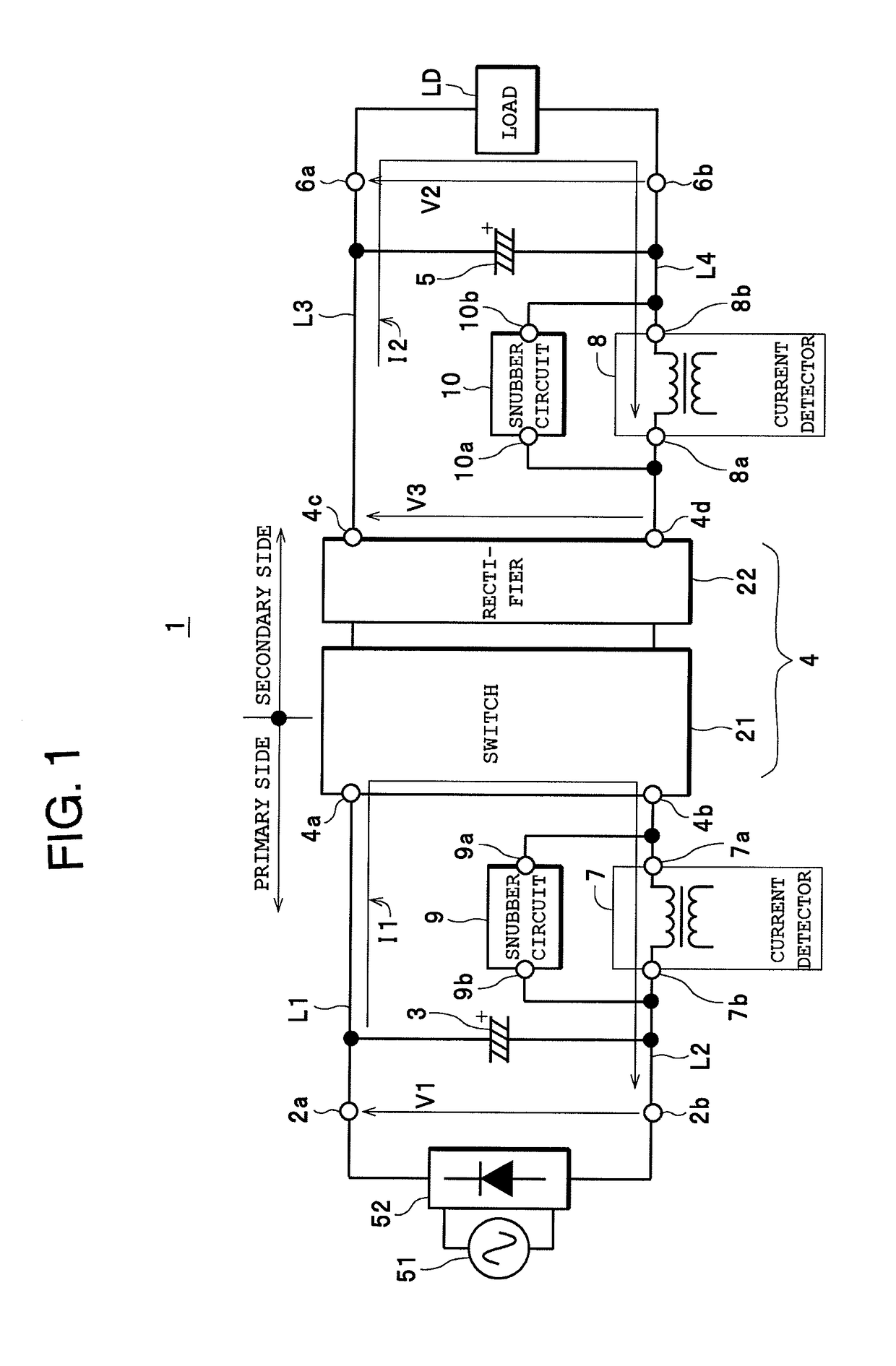
[0018]First, the configuration of an electronic device 1 as one example of an “electronic device” for the present invention will be described with reference to FIG. 1. As one example, the electronic device 1 is a switching power supply device and includes a pair of input terminals 2a and 2b, an input smoothing capacitor 3, a power converter 4, an output smoothing capacitor 5, a pair of output terminals 6a and 6b, a first current detector 7, a second current detector 8, a first snubber circuit 9, and a second snubber circuit 10, and is configured so as to be capable of converting a voltage V1 across both ends of the input smoothing capacitor 3 to an output voltage V2 at the power converter 4 and outputting the output voltage V2 from the pair of output terminals 6a and 6b to a load LD.

[0019]As one example, a rectifier circuit 52 that rectifies (full-wave rectification or h...


PUM


Abstract

An electronic device includes a power converter and a current detector that is disposed at at least one position out of a primary-side position and a secondary-side position for the power converter and detects a current flowing at the at least one position. A snubber circuit including a capacitor is directly connected in parallel to both ends of the current detector.

Description

FIELD OF THE INVENTION[0001]The present invention relates to an electronic device equipped with a power converter and a current detector that is disposed at at least one position out of a primary-side position and a secondary-side position of the power converter and detects a current flowing at the disposed position(s).DESCRIPTION OF THE RELATED ART[0002]As one example of this type of electronic device, a motor driving apparatus disclosed in Patent Literature 1 (see Japanese Laid-open Patent Publication No. 2010-17080 (Pages 4, 5 and FIGS. 1 to 4) is known. This motor driving apparatus includes a rectifier circuit that inputs an alternating current (hereinafter “AC”) power supply, a first capacitor (or “smoothing capacitor”) that is connected across the output terminals of the rectifier circuit, and a three-phase inverter as a power converter that is connected in parallel to the first capacitor, and is configured so as to be capable of supplying the output of the three-phase inverte...

Claims


Application Information

Patent Timeline
Patent Type & Authority Applications(United States)
IPC IPC(8): H02M1/34H02M3/24
CPCH02M1/34H02M3/24H02M2001/0009H02M2001/348H02M2001/346H02M3/28H02M1/348H02M3/337H02M3/335H02M1/0009Y02B70/10H02M1/346
Inventor IKARASHI, TOMOKAZU
Owner TDK CORPARATION
Why Eureka
Try Eureka