
Radiant air conditioning system for heat-producing device

a technology of radiant air conditioning and heat-producing device, which is applied in the direction of refrigeration components, lighting and heating apparatuses, heating types, etc., can solve the problems of insufficient heat transfer by radiant air between them, insufficient heat transfer by convection of air, and a rather low speed

Inactive Publication Date: 2019-01-24
YAN JIGUANG
View PDF7 Cites 3 Cited by
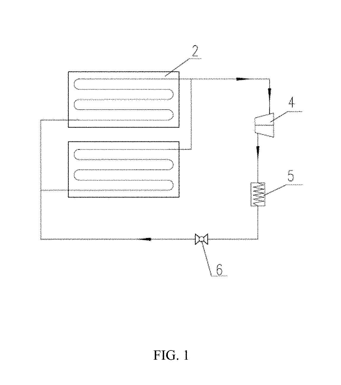
  • Summary
  • Abstract
  • Description
  • Claims
  • Application Information

AI Technical Summary

Benefits of technology

The patent is about a new solution for cooling multiple heat-producing devices using a radiant panel evaporator. Even when there are obstacles in the way, the radiant panel evaporator can still exchange heat with the heat-producing device through a heat transfer plate. This increases the heat transfer paths and improves the heat exchange efficiency. The radiant panel evaporator also includes a layer of thermal insulating material which creates a sealed space for the refrigerant pipe, improving the control of the air conditioning system. This invention is especially useful for cooling dense or stacked heat-producing devices.

Problems solved by technology

But this technical solution is disadvantageous in that there is a limited area for radiant heat transferring between the devices of the base station and the radiant panel, and thus radiant heat transfer between them is not good enough.
In such a case the devices of the base station would still distribute a large amount of heat to the ambient air.
Because heat transfer by convection of air is not good with a rather low speed and thus more energy consumption is required to maintain the devices of the base station at a specified temperature.
When a plurality of base station devices are arranged in the machine room, and particularly when the base station devices are densely arranged, they might block the radiant heat transfer path between the devices of the base station and the radiant panel for each other.
In such a case the drawbacks of this technique becomes particularly obvious.

Method used


Image

  • Radiant air conditioning system for heat-producing device
  • Radiant air conditioning system for heat-producing device
  • Radiant air conditioning system for heat-producing device

Examples


Embodiment Construction

[0005]To solve the above mentioned drawbacks, it is therefore one of the objectives of the present invention to provide a radiant air conditioning system with an improved radiant heat transfer between a radiant panel and a heat-producing device, which is particularly suitable for cooling a plurality of densely distributed heat-producing devices.

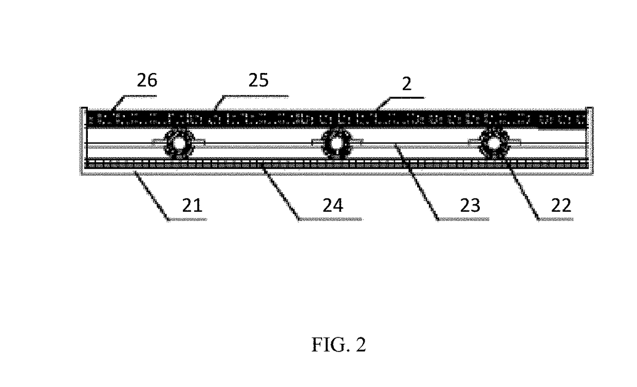
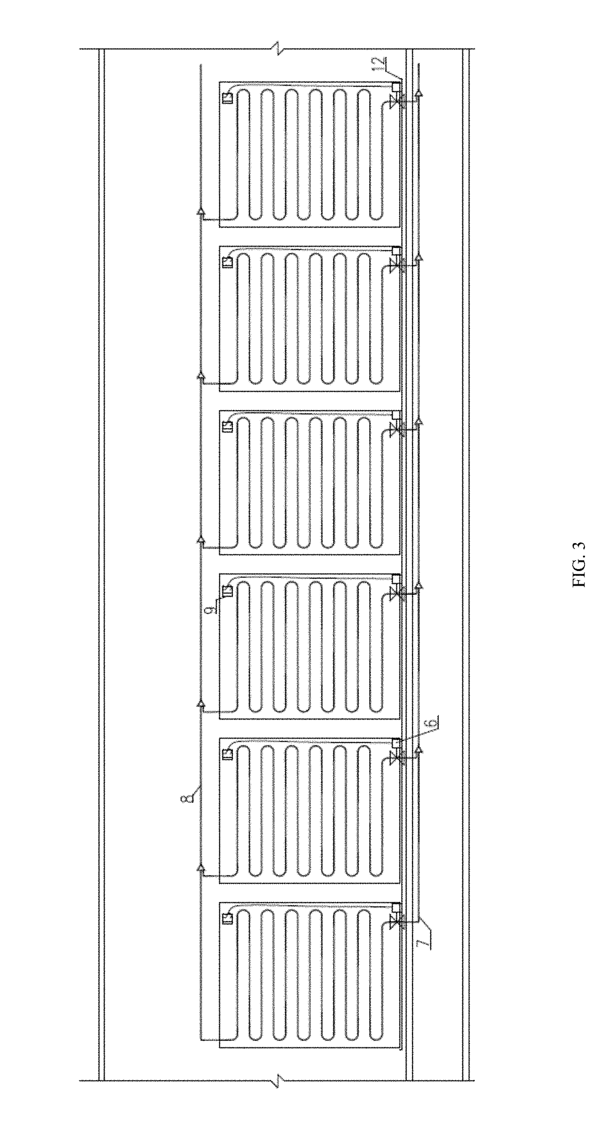
[0006]In order to achieve the above objectives, the present invention provides a radiant air conditioning system for heat-producing devices, comprising a compressor, a condenser, an expansion valve, and at least one radiant panel evaporator which are connected through a connecting pipe to form a recycling refrigerant loop, in which each of the radiant panel evaporators comprises a refrigerant pipe and a radiant panel which exchanges heat with the refrigerant pipe. The radiant air conditioning system further comprises at least one heat transfer plate, configured to perform radiant heat transfer with the heat-producing device, and transmit the ...


PUM


Abstract

The present invention provides a radiant air conditioning system for a heat-producing device (1), comprising a compressor (4), a condenser (5), an expansion valve (6), and at least one radiant panel evaporator (2) which are connected through a connecting pipe to form a recycling refrigerant loop, wherein each of the radiant panel evaporators comprises a refrigerant pipe (22) and a radiant panel (21) which exchanges heat with the refrigerant pipe (22). The radiant air conditioning system further comprises at least one heat transfer plate (3), configured to perform radiant heat transfer with the heat-producing device (1) and transmit an amount of absorbed heat to the radiant panel (21). The present invention improves heat transfer effect between the radiant panel (21) and the heat-producing device (1), and is particularly suitable for cooling a plurality of densely distributed heat-producing devices (1).

Description

FIELD OF THE INVENTION[0001]The present invention relates to a radiant air conditioning system with radiant panel evaporators which is mainly used for cooling electronic heat-producing devices, especially used for cooling various heat-producing devices in a server, a base station etc., and particularly suitable for cooling a plurality of densely distributed heat-producing devices.BACKGROUND OF THE INVENTION[0002]Chinese Invention Patent No. CN200810029359.6 discloses an air conditioning system comprising a radiation heat exchange ceiling plate. The conditioning system comprises a heat pump system and a water circulation system in which the water circulation system comprises a pump, an air heat exchange device, a water heat exchange device and a water circulation loop composed of a plurality of radiation heat exchange ceiling plate. In the conditioning system heat is exchanged with the outside air by means of the air heat exchange device, and heat is also exchanged with the heat pump...

Claims


Application Information

Patent Timeline
IPC IPC(8): F24F5/00H05K7/20F25B41/04
CPCF24F5/0089H05K7/20309H05K7/20318H05K7/20327F25B41/04F25B2600/2513F24F2013/221F25B39/022H05K7/20827F24F5/00H05K7/20
Inventor YAN, JIGUANG
Owner YAN JIGUANG
Learn More