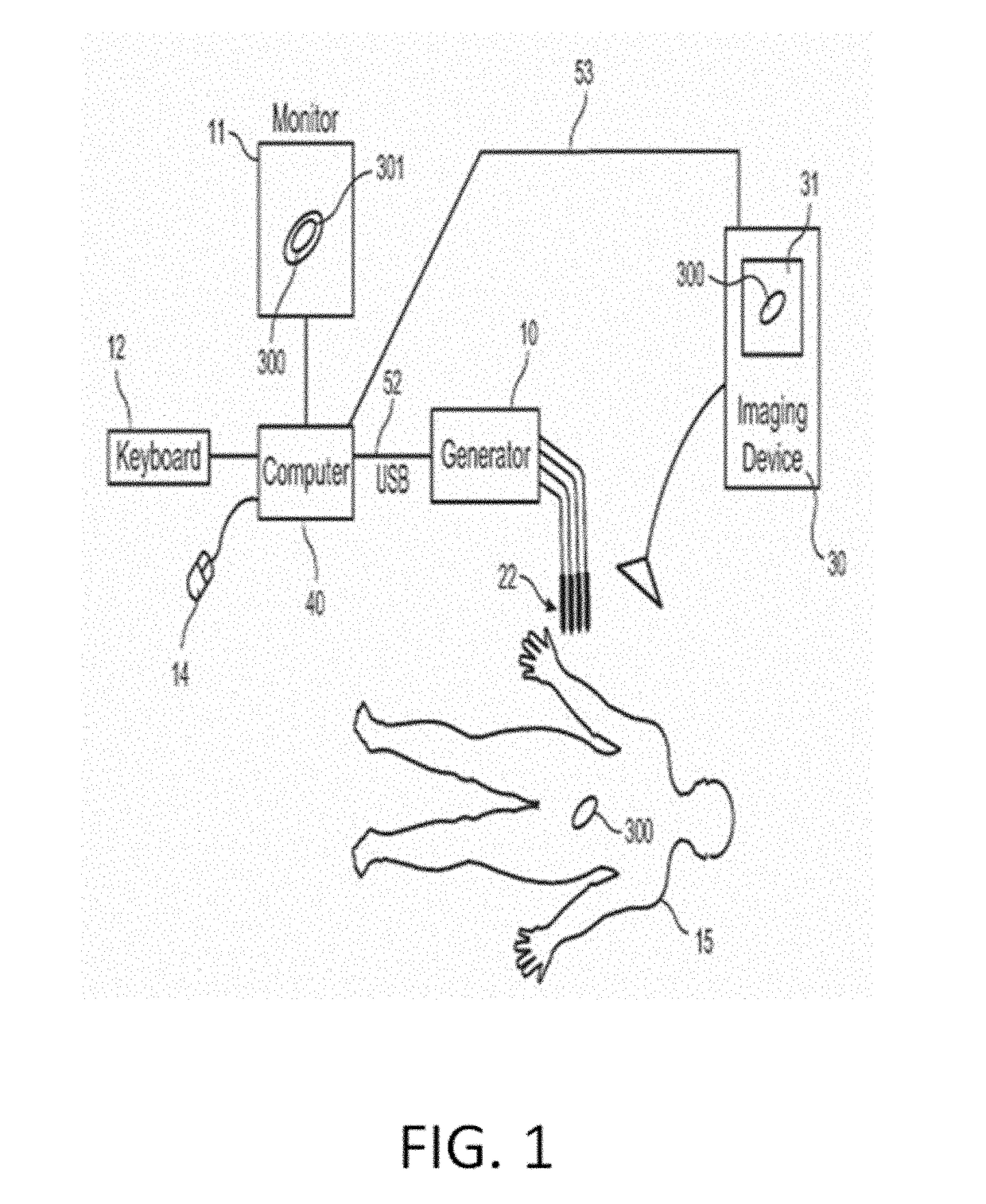
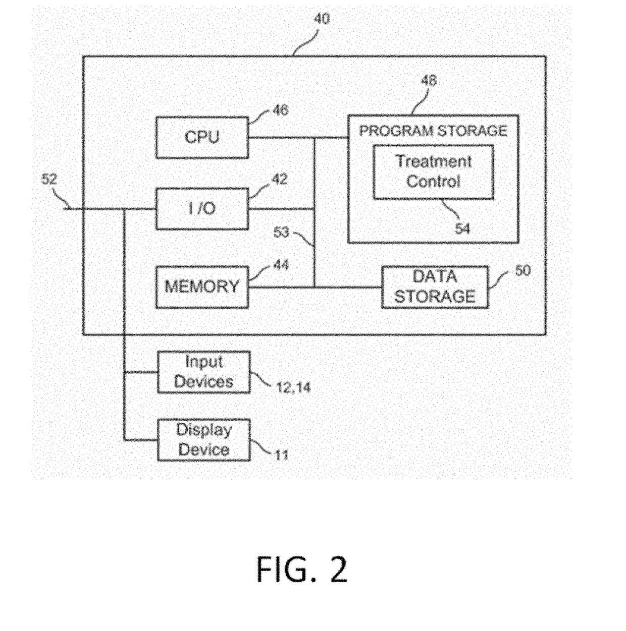
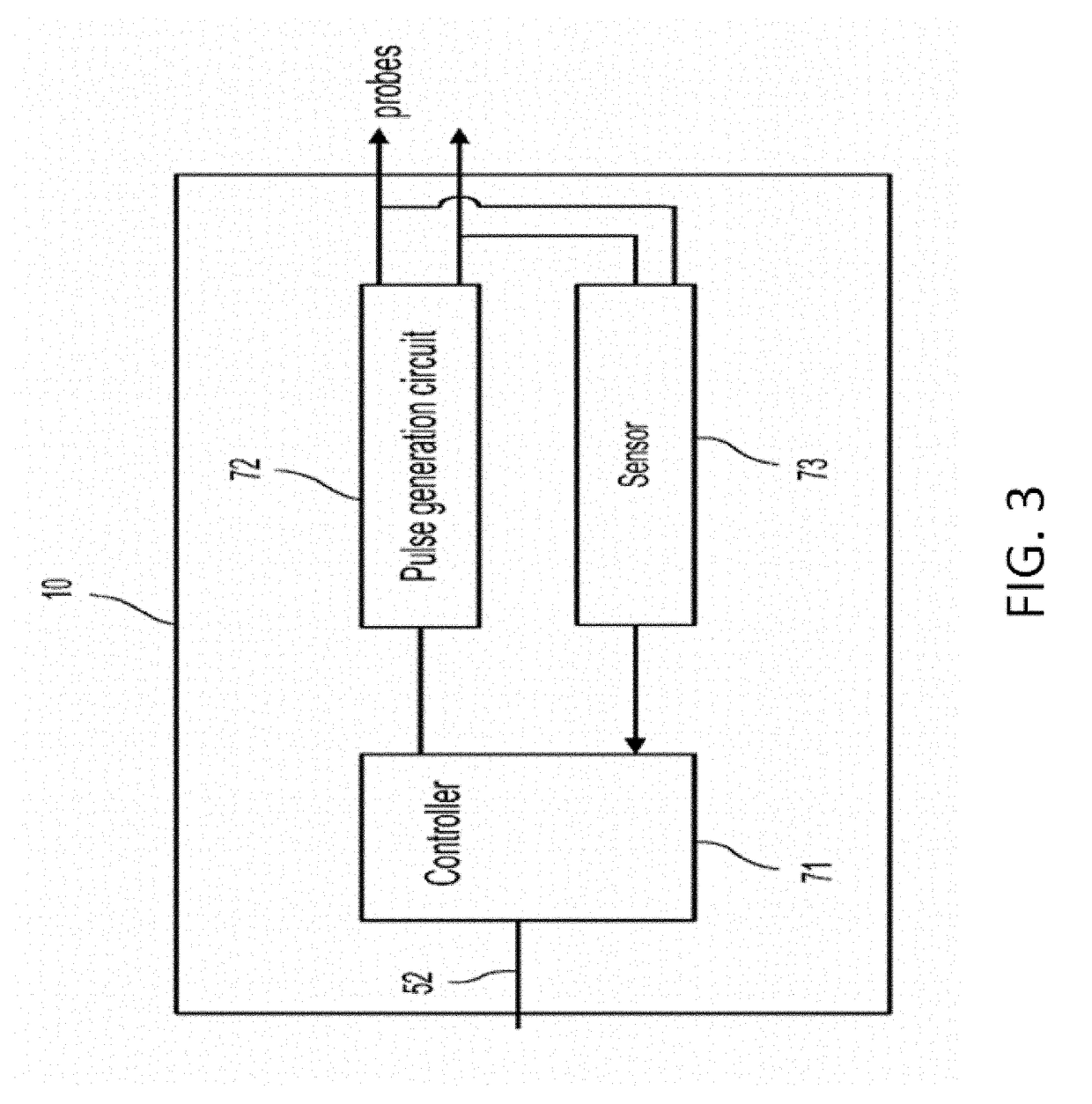
System and method for estimating tissue heating of a target ablation zone for electrical-energy based therapies

a tissue heating and electrical energy technology, applied in the field of medical therapies, can solve the problems of difficult or sometimes impossible to place electrodes in the correct location of the tissue, difficult to predict whether the selected locations will ablate the entire treatment target area, and modest two-dimensional treatment regions may take at least 30 minutes to several hours to compl

Active Publication Date: 2019-01-31
VIRGINIA TECH INTPROP INC
View PDF0 Cites 26 Cited by
  • Summary
  • Abstract
  • Description
  • Claims
  • Application Information

AI Technical Summary

Benefits of technology

[0015]In embodiments, the treatment planning module can be based on a parametric study of the dynamic conductivity curve so that variables related to the dynamic conductivity could be used to fit tissue specific behavior. In embodiments, the treatment planning module may provide input for one or more electrical conductivity parameters such as the baseline (e.g., non-electroporated) conductivity, change in conductivity, the transition zone (how rapidly the conductivity increases), the electric field at which the change in conductivity occurs, and the electric field at which irreversible electroporation occurs. These parameters may be experimentally derived for different tissues and stored in a database. This capability may allow the treating physician to account for different conductivity parameters as they apply to different target tissues when designing a treatment protocol. Thus, when considering a specific tissue, the treating physician may optimize the calculation of an ablation zone for that tissue by inputting one or more of the tissue-specific conductivity parameters for the tissue of interest.

Problems solved by technology

However, if the electrodes are placed by hand in this fashion, it is very difficult to predict whether the locations selected will ablate the entire treatment target area because the treatment region defined by the electrodes vary greatly depending on such parameters as the electric field density, the voltage level of the pulses being applied, size of the electrode and the type of tissue being treated.
Further, it is often difficult or sometimes not possible to place the electrodes in the correct location of the tissue to be ablated because the placement involves human error and avoidance of obstructions such as nerves, blood vessels and the like.
One problem with such a method is that even a modest two dimensional treatment region may take at least 30 minutes to several hours to complete even in a relatively fast personal computer.
This means that it would be virtually impossible to try to obtain on a real time basis different treatment regions based on different electrode positions.
The application of an electric field across any conductive media will result in some degree of resistive losses in which energy is dissipated as heat.
Though cell death in IRE is attributed to non-thermal mechanisms, it is possible to inadvertently elevate tissue temperatures above thermal damage thresholds if parameters are not chosen carefully.
Transient heating of tissue in proximity to the electrode can result in the denaturing of the extracellular matrix, scar formation, or damage to local blood vessels and nerves.

Method used


Image

  • System and method for estimating tissue heating of a target ablation zone for electrical-energy based therapies
  • System and method for estimating tissue heating of a target ablation zone for electrical-energy based therapies
  • System and method for estimating tissue heating of a target ablation zone for electrical-energy based therapies

Examples


example 1

[0169]Materials And Methods

[0170]The tissue was modeled as a 10-cm diameter spherical domain using a finite element package (Comsol 4.2a, Stockholm, Sweden). Electrodes were modeled as two 1.0-mm diameter blunt tip needles with exposure lengths (Y) and edge-to-edge separation distances (X) given in Table 1. The electrode domains were subtracted from the tissue domain, effectively modeling the electrodes as boundary conditions.

TABLE 1Electrode configuration and relevant electroporation-based treatmentvalues used in study.PARAMETER VALUESMEANW [V / cm]500, 1000, 1500, 2000,17502500, 3000X [cm]0.5, 1.0, 1.5, 2.0, 2.51.5Y [cm]0.5, 1.0, 1.5, 2.0, 2.5, 3.01.75Z [cm]1.0, 1.25, 1.5, 2.0, 3.0, 4.0,2.968755.0, 6.0

[0171]The electric field distribution associated with the applied pulse is given by solving the Laplace equation:

∇·(σ(|E|)∇φ)=0  (1)

[0172]where σ is the electrical conductivity of the tissue, E is the electric field in V / cm, and φ is the electrical potential (Edd and Davalos, 2007). Bo...

example 2

ng the Relationship Between Blunt Tip Electrode Configuration and Resulting Current after IRE Treatment

[0181]Model Assumptions:

[0182]Gompertz Conductivity: Pulse duration=50 μs, Ex-vivo kidney tissue

[0183]Baseline Conductivity: σ=0.1 S / m

[0184]Spherical Domain: diameter=10 cm

[0185]Applied Voltage: Voltage=1000 V

[0186]Parametric Study:

[0187]Total Combinations: 720 models

[0188]Maximum Conductivity: 1.0×, 1.25×, 1.5×, 2×, 3×, 4×, 5×, 6× the baseline

[0189]Edge-to-edge Distance: 5, 10, 15, 20, 25 mm

[0190]Electrode Exposure: 5, 10, 15, 20, 25, 30 mm

[0191]Electrode Radius: 0.5, 0.75, 1.0 mm

[0192]The output of statistical analysis software (JMP 9.0) used to fit model and determine the coefficients for all parameter combinations is shown in the tables of FIGS. 8A and 8B and the plot of FIG. 8C.

[0193]Parameters of Best Fit for Dynamic Conductivity Changes Between 1×-6× the Baseline Conductivity (R2=0.96):

[0194]a=−1.428057; (*Intercept Estimate*)

[0195]b=−0.168944; (*Gap Estimate*)

[0196]c=2.1250...

example 3

[0228]Comparison of analytical solutions with statistical (numerical) model to calculate current and explanation of procedure that results in 3D IRE volume.

[0229]The process of backing-out the electrical conductivity using the analytical solutions and the one proposed in the “Towards a Predictive Model of Electroporation-Based Therapies using Pre-Pulse Electrical Measurements” abstract presented in the IEEE Engineering in Medicine and Biology Conference in Aug. 28, 2012 in San Diego, Calif. were compared. A method to determine the predictive power of the equations to calculate current is analyzing the residuals of the 1440 combinations of parameters examined. In the context of this specification, a residual is the difference between the predicted current and the actual current. As can be seen in FIGS. 11A and 11B with increasing non-linear change in conductivity due to electroporation and increasing applied electric field there is an increase in the residual for both cases. The main...


PUM


Abstract

Systems and methods are provided for modeling and for providing a graphical representation of tissue heating and electric field distributions for medical treatment devices that apply electrical treatment energy through one or a plurality of electrodes. In embodiments, methods comprise: providing one or more parameters of a treatment protocol for delivering one or more electrical pulses to tissue through a plurality of electrodes; modeling electric and heat distribution in the tissue based on the parameters; and displaying a graphical representation of the modeled electric and heat distribution. In another embodiment, a treatment planning module is adapted to generate an estimated target ablation zone based on a combination of one or more parameters for an irreversible electroporation protocol and one or more tissue-specific conductivity parameters.

Description

CROSS-REFERENCE TO RELATED APPLICATIONS[0001]The present application is a Continuation of U.S. patent application Ser. No. 14 / 558,631 filed Dec. 2, 2014, which published as U.S. Patent Application Publication No. US 2015 / 0088120 on Mar. 26, 2015. The '631 application is a Continuation-in-Part (CIP) of U.S. patent application Ser. No. 14 / 012,832, filed on Aug. 28, 2013, which published as U.S. Patent Application Publication No. 2013 / 0345697 on Dec. 26, 2013 and issued as U.S. Pat. No. 9,283,051 on Mar. 15, 2016. The '832 application relies on and claims the benefit of the filing date of U.S. Provisional Application No. 61 / 694,144, filed on Aug. 28, 2012. The '832 application is also a CIP of U.S. application Ser. No. 12 / 491,151, filed on Jun. 24, 2009, which '151 application published as U.S. Patent Application Publication No. 2010 / 0030211 on Feb. 4, 2010 and issued as U.S. Pat. No. 8,992,517 on Mar. 31, 2015. The '151 application relies on and claims the benefit of the filing dates ...

Claims


Application Information

Patent Timeline
Patent Type & Authority Applications(United States)
IPC IPC(8): A61B18/14
CPCA61B18/1477A61B2018/00892A61B2018/00779A61B2018/00875A61B2018/00886A61B90/37A61B2034/256A61B34/10A61B2018/1425A61B2018/0016A61B34/25A61B2018/00613C12N13/00A61B2034/104
Inventor GARCIA, PAULO A.ARENA, CHRISTOPHER B.SANO, MICHAEL B.DAVALOS, RAFAEL V.
Owner VIRGINIA TECH INTPROP INC
Why Eureka
Try Eureka