Industrial cleaning installation with a filter arrangement and corresponding process

a technology of industrial cleaning and filter arrangement, applied in the field of industrial cleaning, can solve the problems of high system running cost, inconvenient cleaning process, inefficiency of system, etc., and achieve the effects of low maintenance cost, efficient separation from cleaning liquid, and simple and reliabl

Inactive Publication Date: 2019-01-31
ELWEMA AUTOMOTIVE
View PDF0 Cites 5 Cited by
  • Summary
  • Abstract
  • Description
  • Claims
  • Application Information

AI Technical Summary

Benefits of technology

[0009]The industrial installation as proposed in claim 1 includes a filter arrangement comprising a first filter which is a backwash filter for receiving contaminated cleaning liquid, and a second filter arranged for receiving backwashed contaminated cleaning liquid from the backwash filter, and for removing solid matter from the contaminated cleaning liquid. The installation further comprises an oil separator arranged for receiving contaminated cleaning liquid and for removing oil from the contaminated cleaning liquid. The inventors have found that by arranging the oil separator to receive contaminated cleaning liquid directly from the second filter, instead of from a tank which is directly fed by the outlet from a cleaning bath, the path distance for the recycled cleaning liquid can be reduced. It is also not necessary to provide a pump to pump large amounts of contaminated cleaning liquid from the contaminated cleaning liquid tank to the oil separator. The invention therefore results in an increased energy efficiency and lower running costs for the cleaning installation.
[0011]In a further embodiment a contaminated cleaning liquid tank is provided for receiving contaminated cleaning liquid from a cleaning bath, whereby the backwash filter is arranged to receive contaminated cleaning liquid directly from the contaminated cleaning liquid tank, and the backwash filter is arranged to supply filtered cleaning liquid to cleaning nozzles or to a cleaning bath for cleaning a workpiece. The contaminated cleaning liquid tank may advantageously be provided with an oil skimmer for skimming an emulsion of oil and cleaning liquid from the surface of the cleaning liquid tank and supplying it to the oil separator. This method has the advantage that the average fluid path length for the oil before it is separated from the cleaning liquid in the oil separator is reduced.
[0012]In a further preferred embodiment the second filter is a belt filter. The belt filter has the advantage that it is simple and reliable with low maintenance needs. A belt filter can also be adjusted to separate the solid matter from the cleaning liquid at required rate, depending on the workpieces to be cleaned. In another embodiment the second filter is a combination of at least two filters, whereby each filter is configured to optimally remove a different size particle. This has the advantage that a wide range of debris particle sizes can be efficiently separated from the cleaning liquid.
[0013]The oil separator is preferably a gravity separation device. This has the benefit that it is a simple, low maintenance device, so that the running costs can be minimized. The oil separator is preferably fluidly connected to the contaminated cleaning liquid tank for returning cleaning liquid to the contaminated cleaning liquid tank and fluidly connected to an oil container for collecting the separated oil.
[0014]In a further preferred embodiment the second filter is arranged on top of the oil separator which is arranged on top of the contaminated cleaning liquid tank such that gravity assists the flow of contaminated cleaning liquid from the second filter to the contaminated cleaning liquid tank. This arrangement has the advantage that the path lengths for the contaminated cleaning liquid are as short as possible and energy required to pump the contaminated cleaning liquid through the system is reduced.
[0015]Furthermore the contaminated cleaning liquid tank may comprise an oil skimmer for removing oil from the surface of the contaminated cleaning liquid in the contaminated cleaning liquid tank. In this preferred embodiment an emulsion of oil and cleaning liquid can be skimmed from the top of the contaminated cleaning liquid tank and fed to the oil separator. The oil separator therefore receives an emulsion of contaminated liquid and oil from the second filter and from the contaminated cleaning liquid tank, whereby this arrangement has a synergetic effect to optimally remove the oil from the contaminated cleaning liquid in a short path.

Problems solved by technology

It is not readily suitable for removing oil-like contaminants such as emulsified oils and / or fats.
The system is however inefficient as the oil and cleaning liquid mixture is pumped from the contaminated liquid tank to the oil separator, requiring a pump, which results in high system running costs.
This system therefore requires good maintenance, increasing process costs.

Method used


Image

  • Industrial cleaning installation with a filter arrangement and corresponding process
  • Industrial cleaning installation with a filter arrangement and corresponding process

Examples


Embodiment Construction

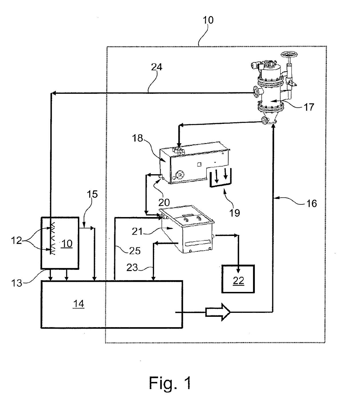
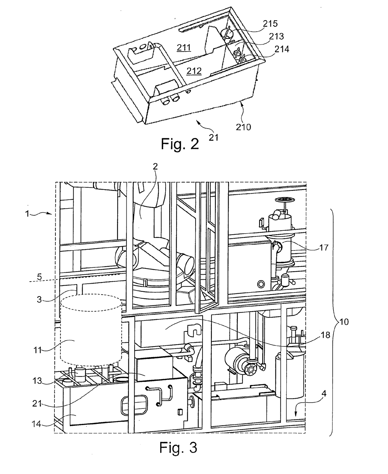
[0027]Referring to FIG. 1, which schematically shows a filter arrangement 1 for an industrial cleaning installation, initially an industrial process is described for cleaning machined workpieces. The workpieces are for example engine or transmission components such as cylinder blocks, and have been machined for example by drilling, milling, grinding or turning. The machining process may require the use of lubricants, chip removers, rust inhibitors and coolants. Residues of these liquids along with any chips or burrs remaining on the workpiece must therefore be removed from the part after machining. For this purpose the workpiece is subject to a cleaning operation in a cleaning receptacle 11 containing a bath of cleaning liquid. The workpiece may be moved to the cleaning receptacle 11 by a conveyor or by an industrial robot (see FIG. 3). Cleaning liquid, which may be water or an aqueous cleaning liquid using water as a solvent is sprayed onto the work piece through a plurality of noz...


PUM

PropertyMeasurementUnit
sizeaaaaaaaaaa
shapeaaaaaaaaaa
shapesaaaaaaaaaa

Abstract

An industrial installation and process for cleaning workpieces, in particular for cleaning components of engines and transmission components using a cleaning liquid, includes a first filter which is a backwash filter (17) for receiving contaminated cleaning liquid. A second filter (18) is arranged for receiving backwashed contaminated cleaning liquid from the backwash filter (17), and for removing solid matter, e.g. chips, from the contaminated cleaning liquid. An oil separator (21) is arranged for receiving contaminated cleaning liquid and for removing oil from the contaminated cleaning liquid. The oil separator (21) is fluidly connected to the second filter (18) and arranged for receiving the contaminated cleaning liquid directly from the second filter (18). The arrangement of the oil separator (21) directly following the second filter improves the filtering efficiency of the system by reducing the flow path distances of the contaminated cleaning liquid.

Description

TECHNICAL FIELD[0001]The present invention generally relates to the field of industrial cleaning of machined workpieces, and more particularly to method and industrial installation for removing waste matter from the cleaning liquid for use in subsequent cleaning of the machined workpieces.[0002]The process of machining a metal workpiece to produce finished parts, for example engine and transmission components, such as cylinder heads, cylinder blocks, gearbox-casings etc., requires that a cutting tool of some sort is used to remove material from the workpiece to achieve the desired shape of the finished part. The machining operation may include drilling, milling, grinding or turning. After these machining operations burrs remain on the workpiece which are raised edges or small pieces of material remaining attached to the workpiece. These must be removed along with any remaining cutting chips and other particle matter from the machining process. Because the machining process may also ...

Claims


Application Information

Patent Timeline
Patent Type & Authority Applications(United States)
IPC IPC(8): B08B3/14B01D17/00B01D17/02
CPCB08B3/14B01D17/08B01D17/0208B01D17/00B01D36/02B01D36/04
Inventor ALVAREZ, ANTONIOSONNTAG, DIETMAR
Owner ELWEMA AUTOMOTIVE
Why Eureka
Try Eureka