Manufacturing method for metal grating, metal grating and display device

a manufacturing method and metal grating technology, applied in the field of display technologies, can solve the problems of inability to apply in an actual product, nano-imprinting procedure has a lower yield rate, and requires more complicated processes, and the manufacturing cost is higher

Active Publication Date: 2019-02-07
BOE TECH GRP CO LTD +1
View PDF3 Cites 2 Cited by
  • Summary
  • Abstract
  • Description
  • Claims
  • Application Information

AI Technical Summary

Benefits of technology

[0006]According to a possible implementation, in the manufacturing method provided by an embodiment of the present disclosure, the thickness of the metal thin film is smaller than half of a pitch between adjacent grating s

Problems solved by technology

Therefore, it cannot be applied in an actual product.
However, the nano-imprinting procedure has a lower yield rate a

Method used


Image

  • Manufacturing method for metal grating, metal grating and display device
  • Manufacturing method for metal grating, metal grating and display device
  • Manufacturing method for metal grating, metal grating and display device

Examples


Embodiment Construction

[0026]Specific implementations of the manufacturing method for a metal grating, the metal grating and the display device provided in embodiments of the present disclosure will be described below in detail with reference to the drawings.

[0027]In the drawings, thicknesses and shapes of each thin film do not reflect the real ratio of the metal grating. But instead, they are only provided to illustrate contents of the present disclosure schematically.

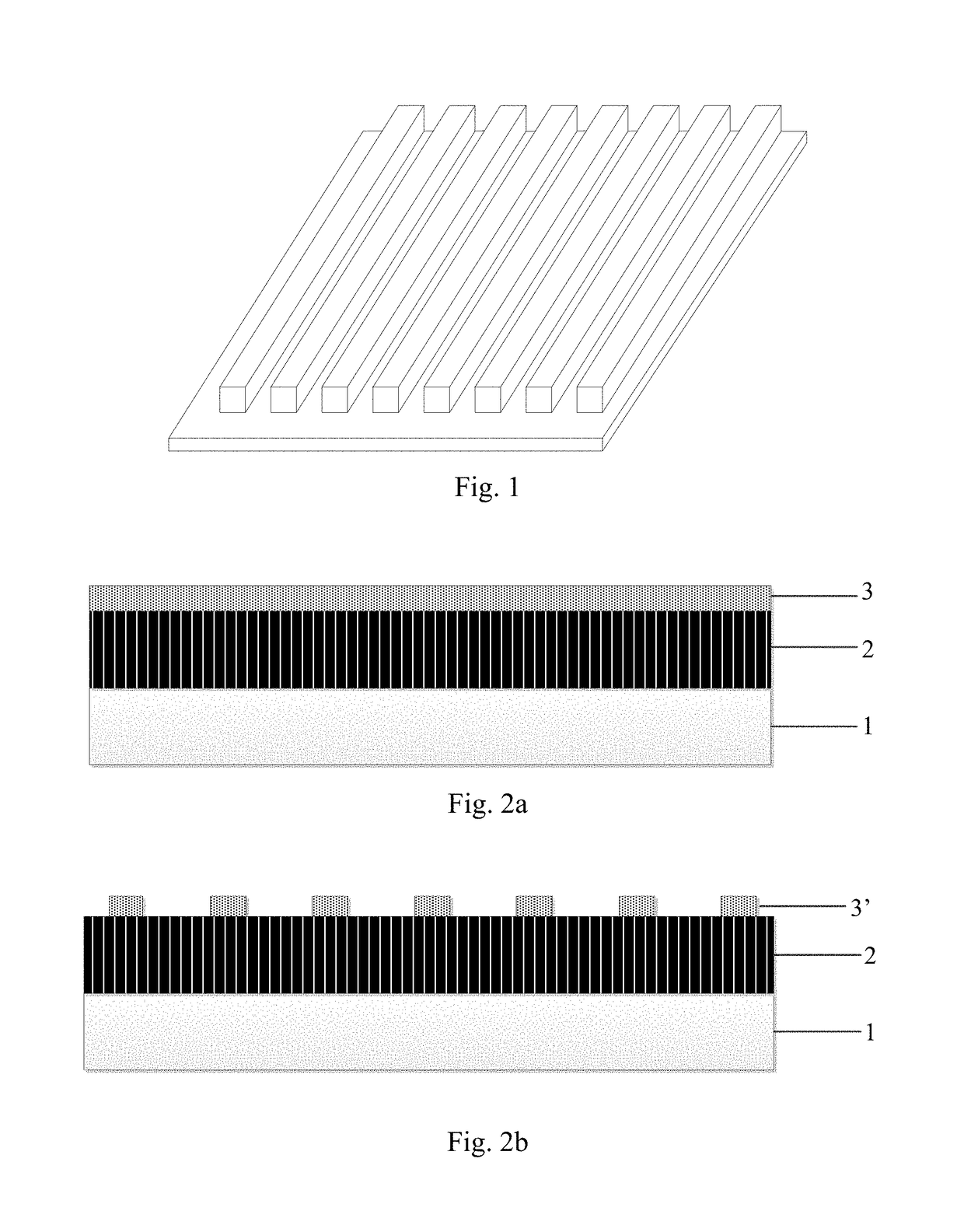
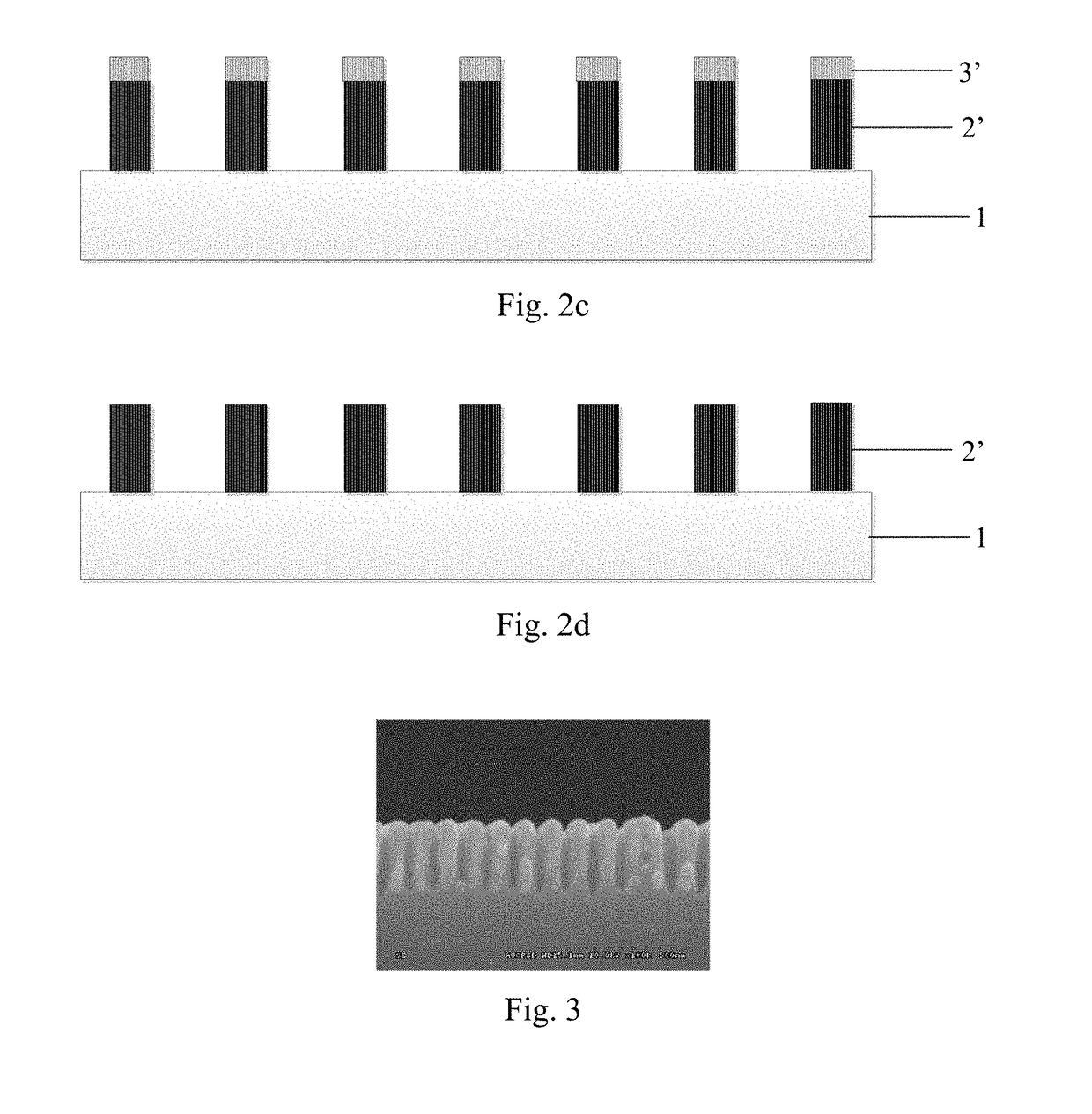
[0028]Referring to FIG. 1, a schematic structure view for a typical metal grating is shown. Specifically, as shown in FIG. 1, the metal grating can be used as a built-in polarizer inside a display device. Next, the manufacturing process for the metal grating shown in FIG. 1 will be described in detail with reference to FIG. 2. As an example, the manufacturing process can comprise steps of: (1) as shown in FIG. 2a, depositing a metal film 2 on a base 1 and continuing to apply an adhesive film 3; (2) as shown in FIG. 2b, patterning the adhesi...


PUM

PropertyMeasurementUnit
Thicknessaaaaaaaaaa
Widthaaaaaaaaaa
Fluidityaaaaaaaaaa

Abstract

The present disclosure relates to a manufacturing method for a metal grating, a metal grating, and a display device. In this manufacturing method, after forming a plurality of parallel grating strips by means of an adhesive film layer, a metal thin film with a uniform thickness is formed over the plurality of grating strips and gaps between the grating strips. Furthermore, a metal grating is formed by performing topping treatments on both of an upper surface and a lower surface of the resulting structure.

Description

CROSS REFERENCE TO RELEVANT APPLICATION(S)[0001]The present application claims the priority of the Chinese patent application No. 201710648516.0 filed on Aug. 1, 2017, the entire disclosure of which is incorporated herein by reference.TECHNICAL FIELD[0002]The present disclosure relates to the field of display technologies, and in particular to a manufacturing method for a metal grating, a metal grating, and a display device.BACKGROUND ART[0003]At present, in a flat panel display, for fabricating a built-in polarizer, a dichroic dye is usually used as a main component of the polarizer, and applied inside a liquid crystal cell by spin-coating, so as to form the built-in polarizer. Due to limitations of the material, a polarizer formed in this way has only a polarization degree of 80%, which is far from the polarization degree of 99.99% as required by a display panel. Therefore, it cannot be applied in an actual product.[0004]As an alternative formation approach, the built-in polarizer...

Claims


Application Information

Patent Timeline
IPC IPC(8): G02B5/30C23F4/00G02F1/1335H01L51/52
CPCG02B5/3041C23F4/00G02F1/133528H01L51/5281G02F2201/30G02B5/1847G02B5/1857H10K59/8791G02B5/3058G02F1/133548G02F1/133565H10K50/86
Inventor QU, LIANJIE
Owner BOE TECH GRP CO LTD
Why Eureka
Try Eureka