Distributed Wireless Charging System and Method
- Summary
- Abstract
- Description
- Claims
- Application Information
AI Technical Summary
Benefits of technology
Problems solved by technology
Method used
Image

Examples
example 1
[0114]A prototype implementation was developed to demonstrate distributed energy beamforming to power sensor nodes. FIG. 14A shows the prototype setup, which included two programmable ETs, an RF-energy harvester circuit, and a controller. The programmable ETs were each based on a Universal Software Radio Peripheral (USRP) B210, manufactured by Ettus Research LLC, as a software-defined radio connected to a power amplifier. The USRPs were controlled with the open source USRP hardware driver (UHD), and GNURadio software. The prototype included features such as frequency synchronization, phase synchronization, and phase adjustments for forming constructive energy beams, as described above. The RF-energy harvester was fabricated and connected to a sensor device (TI EZ430) to convert RF-to-DC with high efficiency.
[0115]The RF energy harvesting circuit included an antenna, an impedance matching network sub-circuit, a 4-stage diode-based Dickson voltage rectifier, and a 3300 μF capacitor fo...
example 2
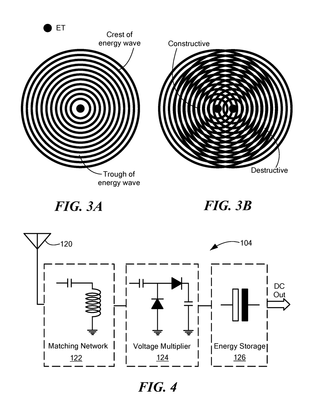
[0120]As noted above, FIG. 3 illustrates two-dimensional patterns of transferred energy produced by multiple ETs. Concurrent energy transmissions at the same frequency cancel the transferred energy in destructive areas and aggregate energy in constructive areas. Through experimental measurements, FIG. 15 illustrates the effects of constructive and destructive combinations of energy waves from two ETs. Here, the two ETs transferred energy with random initial phases at 915 MHz each with an output power of 3 Watts. The ET and RF energy harvesting circuits had antenna gains of 1 dBi and 6.1 dBi, respectively, and the capacitor storage of the receiver node was C=100 mF. The total harvested power was measured while varying the distances between energy transmitters and the receiver, which led to the different phase separations of the arriving energy waves. It can be observed that destructive interference from one ET strongly affected the energy transmitted by another ET, and at distances, ...
example 3
[0121]A prototype of a dual-stage RF energy harvesting device was developed, illustrated in FIG. 16, for operation in both low power and high power regions. The prototype of the dual-stage energy harvesting circuit was based on the voltage multiplier. The prototype was designed considering all input parameters needed to obtain high power conversion efficiency from the RF energy harvester. The main components of prototype and parameters that influenced the efficiency and performance of the circuit included the multiplier topology, nonlinear components of the multiplier, and the number of stages.
[0122]The multiplier topologies do not demonstrate a significant difference in performance. Hence, a Dickson topology (FIG. 17), which has a parallel configuration of capacitors in each stage, was chosen. This topology was advantageous in this implementation because with the capacitors connected in parallel, the effective circuit impedance was reduced. This made the task of matching the antenn...
PUM
 Abstract
Description
Claims
Application Information
 - R&D
- Intellectual Property
- Life Sciences
- Materials
- Tech Scout
- Unparalleled Data Quality
- Higher Quality Content
- 60% Fewer Hallucinations
Browse by: Latest US Patents, China's latest patents, Technical Efficacy Thesaurus, Application Domain, Technology Topic, Popular Technical Reports.
© 2025 PatSnap. All rights reserved.Legal|Privacy policy|Modern Slavery Act Transparency Statement|Sitemap|About US| Contact US: help@patsnap.com