
Machine learning three-dimensional fluid flows for interactive aerodynamic design

a technology of three-dimensional fluid flow and design object, applied in the field of computational flow dynamics, can solve the problems of computationally expensive, time-consuming, and complex cfd, and achieve the effect of efficient optimization of the shape of the design obj

Active Publication Date: 2019-02-14
AUTODESK INC
View PDF0 Cites 20 Cited by
  • Summary
  • Abstract
  • Description
  • Claims
  • Application Information

AI Technical Summary

Benefits of technology

The patent provides a technique for faster and more efficient computer simulation of fluid flows, which allows engineers and designers to visualize the effects of changes to the shape of their objectives in real-time or near real-time. This technique allows for more efficient optimization of design objects based on aerodynamic considerations.

Problems solved by technology

One drawback to implementing CFD in the design process is that CFD is computationally expensive and complex and quite time consuming.
As a result, iteratively optimizing the shape of the design object via CFD would take hours or even more than a day to complete.

Method used


Image

  • Machine learning three-dimensional fluid flows for interactive aerodynamic design
  • Machine learning three-dimensional fluid flows for interactive aerodynamic design
  • Machine learning three-dimensional fluid flows for interactive aerodynamic design

Examples


Embodiment Construction

[0017]In the following description, numerous specific details are set forth to provide a more thorough understanding of the present invention. However, it will be apparent to one of skill in the art that embodiments of the present invention may be practiced without one or more of these specific details.

Hardware Overview

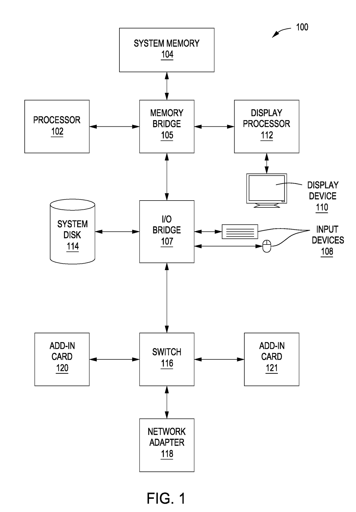
[0018]FIG. 1 is a block diagram illustrating a computer system 100 configured to implement one or more aspects of the present invention. This figure in no way limits or is intended to limit the scope of the present invention. Computer system 100 may be a mainframe, minicomputer, personal computer, video game console, personal digital assistant, mobile phone, mobile device or any other device suitable for practicing one or more embodiments of the present invention.

[0019]As shown, computer system 100 includes, without limitation, a central processing unit (CPU) 102 and a system memory 104 communicating via a bus path that may include a memory bridge 105. CPU 102 include...


PUM


Abstract

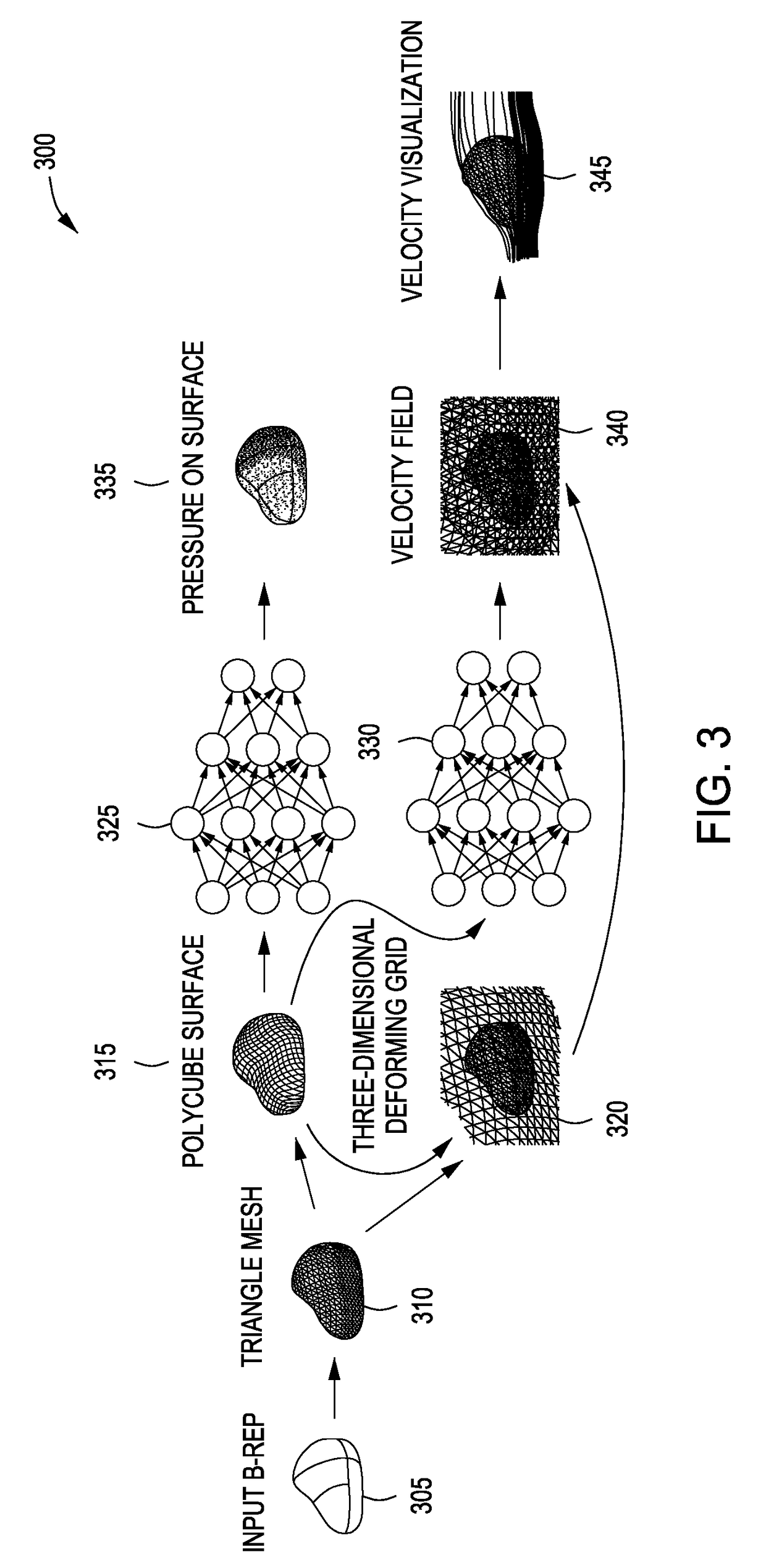
Embodiments of the invention disclosed herein provide techniques for simulating a three-dimensional fluid flow. A parameterization application parameterizes a first representation of a design object to compute a first polycube representation. The parameterization application computes a first distortion grid based on the first polycube representation. A machine learning application computes, via a first neural network, a surface pressure model based on the first polycube representation. The machine learning application computes, via a second neural network, a velocity field model based on the first polycube representation and the first distortion grid. The machine learning application generates a visualization of the surface pressure model and the velocity field model for display on a display device.

Description

BACKGROUND OF THE INVENTIONField of the Invention[0001]The present invention relates generally to computational flow dynamics (CFD) and, more specifically, to machine learning three-dimensional fluid flows for interactive aerodynamic design.Description of the Related Art[0002]In the field of field of engineering and computational fabrication, fluid flow simulation is often employed by engineers and designers for the purpose of design evaluation and optimization. One such fluid simulation technique is referred to herein as “computational fluid dynamics” (CFD). Via techniques such as CFD, engineers and designers can simulate the flow of a fluid, such as a liquid or gas, around an arbitrary object. These objects are referred to herein as “design objects.” A proper CFD simulation enables the engineer or designer to view the velocity field of the fluid around the design object over a period of time as well as the pressure applied by the fluid on the surface of the object over that same p...

Claims


Application Information

Patent Timeline
IPC IPC(8): G06F17/50G06T19/20G06T17/20G06N3/02
CPCG06F17/5009G06N3/02G06T17/20G06T19/20G06N3/084G06F30/20G06F2111/10G06N3/045G06N3/04
Inventor UMETANI, NOBUYUKI
Owner AUTODESK INC
Learn More