MRI and ct contrast-enabled composite implants for image-guided tissue regeneration and therapy

a tissue regeneration and composite implant technology, applied in the field of composite implants for tissue regeneration, can solve the problem of restricting the application of mri and ct for tissue regeneration

Active Publication Date: 2019-02-21
AMRITA VISHWA VIDYAPEETHAM
View PDF2 Cites 2 Cited by
  • Summary
  • Abstract
  • Description
  • Claims
  • Application Information

AI Technical Summary

Benefits of technology

[0009]In one embodiment, the doped calcium nano or micro particles are loaded onto the composite implant from 1-95% by weight of the composite implant. In one embodiment, the biopolymer further comprises one or more agents configured to be released from the composite implant into human or animal tissue. In one embodiment, the 3-dimensional interconnected porosity is configured to provide sites for proliferation and osteogenic differentiation of mesenchymal stem cells.
[0010]Further, the present subject matter provides a method of making composite implant capable of providing imaging contrast for magnetic resonance (MRI) and computed tomography (CT). The method comprises mixing one or more precursors for forming a calcium compound in an aqueous solution, adding a first dopant configured to provide MR contrast at a first concentration and a second dopant configured to provide CT contrast at a second concentration, precipitating particles of the calcium compound doped with the first dopant and the second dopant from solution. The first dopant and the second dopant together form 0.0001-50 wt % of the calcium compound. The precipitate particles then washed to remove impurities. To form the composite implant, a suspension of the redispersed particles is mixed with a biopolymer to form a gel. The gel is then lyophilized to form a porous body. The porous body is further crosslinked to form the composite implant. In one embodiment, the method further comprises an additional lyophilizing step after cross-linking.
[0011]In one embodiment, the method further comprises adding one or more therapeutic agents to the biopolymer prior to gel formation wherein the one or more agents are configured to be released from the composite implant into human or animal tissue. In one embodiment, the one or more agents include a drug, a growth factor or a bioactive molecule.

Problems solved by technology
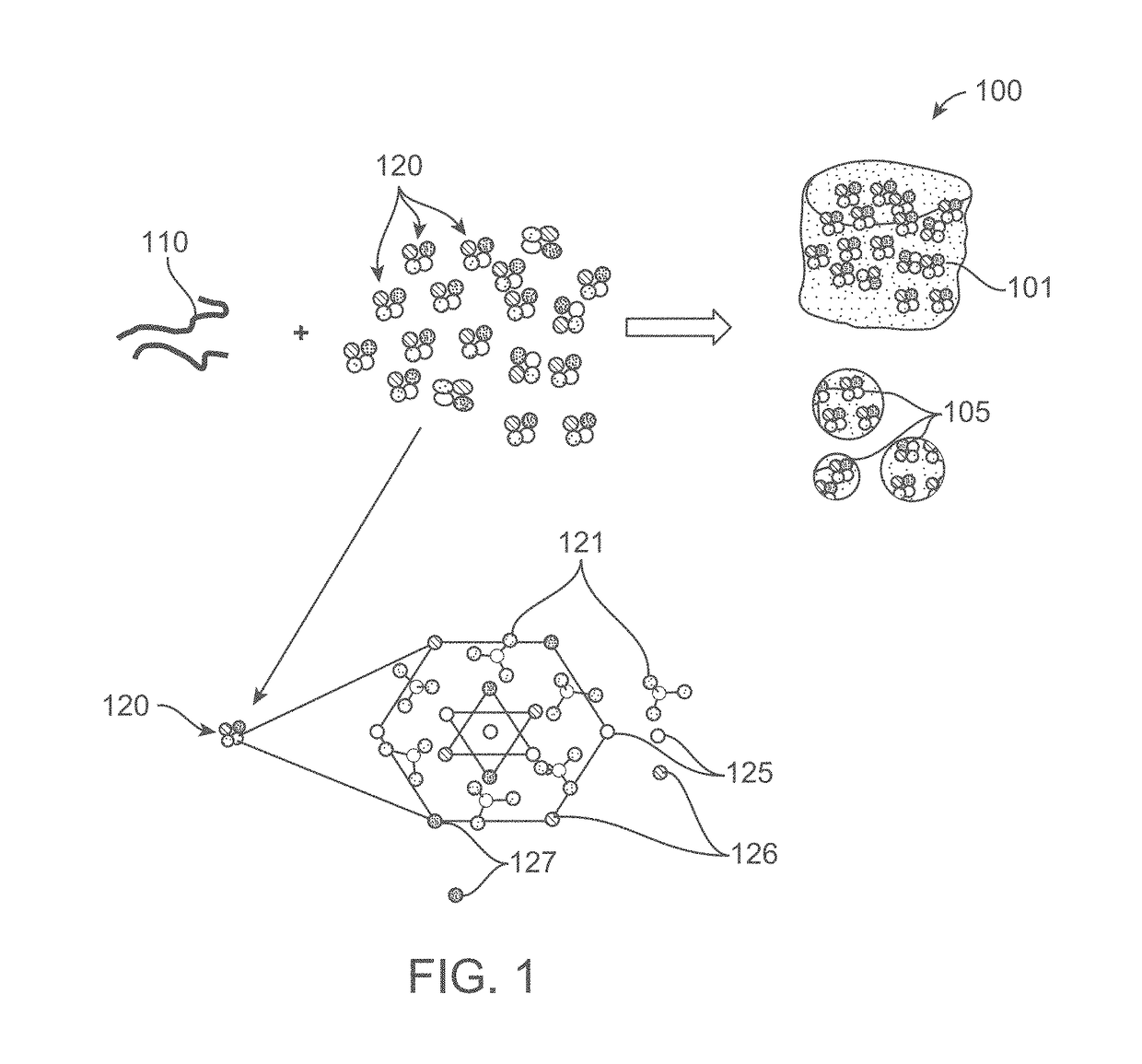
However, insignificant difference in contrast change between host tissue and implanted biomaterial based scaffold often limits the application of MRI and CT for detecting tissue regeneration.

Method used


Image

  • MRI and ct contrast-enabled composite implants for image-guided tissue regeneration and therapy
  • MRI and ct contrast-enabled composite implants for image-guided tissue regeneration and therapy
  • MRI and ct contrast-enabled composite implants for image-guided tissue regeneration and therapy

Examples


example 3

ization of 3-D Scaffold / Bead

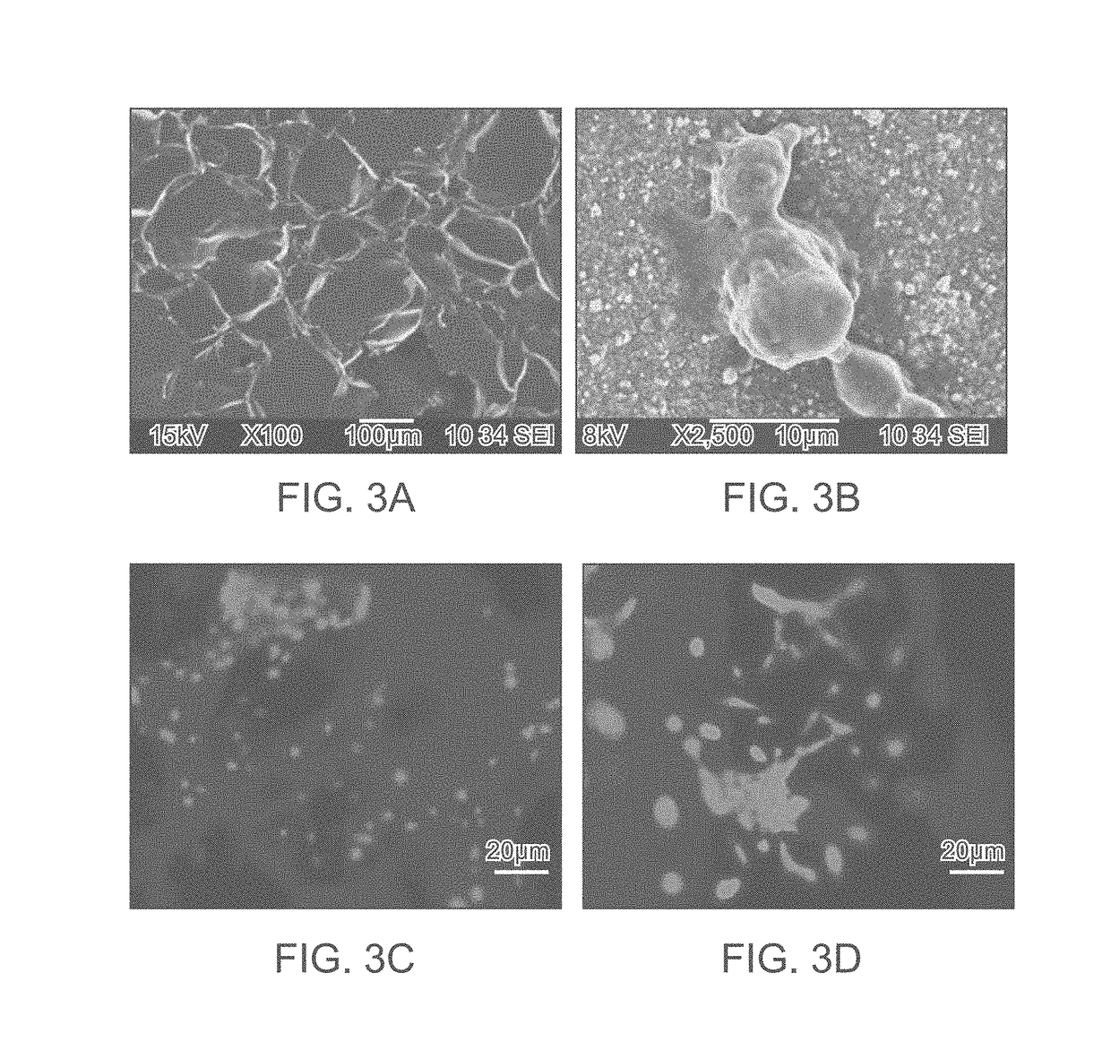
[0057]Porous morphology of the developed scaffold is evident from SEM image in FIG. 3A. Pore size of the scaffold ranging from 150-200 μm, as shown in FIG. 3A, facilitates cell growth and proliferation. FIGS. 3B and 3C represent SEM images of mesenchymal stem cells (MSCs) attachment and cell spreading using nuclear staining with DAPI on the scaffold respectively. FIG. 3D represents live / dead imaging of MSCs proving the biocompatibility of the scaffold.

[0058]Nano- or micro-doped HAp incorporated scaffold provides an enhanced T2 contrast compared to undoped scaffold due to the T2 shortening by Fe3+ ions. FIG. 4A shows the change in MRI contrast with increasing concentration of doped nano-micro HAp from 0-50% and FIG. 4B represents CT images of 3-D scaffold showing change in contrast with respect to incorporation of nano- or micro-particle doped HAp.

[0059]FIG. 5A shows photograph of phantom bone sample filled with doped beads 105. FIG. 5B is a sagittal secti...


PUM

PropertyMeasurementUnit
sizeaaaaaaaaaa
timeaaaaaaaaaa
magnetic resonance imagingaaaaaaaaaa

Abstract

A composite implant for providing simultaneous magnetic resonance imaging (MRI) and computed tomographic (CT) imaging contrast is disclosed. The composite implant is formed of a calcium compound in the form of nano or microparticles doped with a first dopant configured to provide MRI contrast and a second dopant configured to provide CT contrast. The calcium compound is loaded onto a polymer gel matrix and lyophilized to form a mass with 3-dimensionally interconnected porosity, configured to provide tissue integration and proliferation sites. Methods of forming the composite implant are also disclosed. The implant could be a scaffold or bead structured to enable treatment of human or animal patient for bone/cartilage injury or defect by implantation, with MRI and CT monitoring.

Description

CROSS-REFERENCES TO RELATED APPLICATIONS[0001]This application is a National Stage of International application No. PCT / US2017 / 020793 entitled “MRI AND CT CONTRAST-ENABLED COMPOSITE IMPLANTS FOR IMAGE-GUIDED TISSUE REGENERATION AND THERAPY” filed on Mar. 3, 2017, which claims priority to Indian Provisional Patent Application No. 201641007472 entitled “MRI AND CT CONTRAST ENABLED 3D SCAFFOLDS AND BEADS FOR IMAGE GUIDED TISSUE REGENERATION”, filed on Mar. 3, 2016, the full disclosure of which is incorporated herein by reference.FIELD OF THE INVENTION[0002]The invention generally relates to composite implants for tissue regeneration and in particular to osteoconductive 3-D scaffold and beads, method of preparation thereof and use thereof in magnetic resonance imaging (MRI) and / or computed tomography (CT) contrast enabled treatment.BACKGROUND[0003]Non-invasive monitoring of tissue regeneration is turning out to be of particular importance as it can provide information about various stag...

Claims


Application Information

Patent Timeline
Patent Type & Authority Applications(United States)
IPC IPC(8): A61K49/18A61B6/00A61L27/02A61L27/22A61L27/20A61L27/44A61L27/56A61B5/055A61L27/54A61K49/14A61K49/04G01R33/48G01R33/56
CPCA61K49/1818A61B6/481A61L27/025A61L27/222A61L27/20A61L27/446A61L27/56A61B5/055A61L27/54A61K49/14A61K49/04G01R33/4812G01R33/5601A61L2300/414A61L2430/00A61K9/0024A61K49/0419A61K49/0457A61K49/1803A61K47/02A61K47/36A61K47/42A61K9/19G01R33/58A61K49/0002A61L27/46A61L27/50A61L2430/02A61L2400/12
Inventor KOYAKUTTY, MANZOORMEETHALEVEEDU, SAJESH K.ASHOKAN, ANUSHASOMASUNDARAM, VIJAY HARISHNAIR, SHANTIKUMAR
Owner AMRITA VISHWA VIDYAPEETHAM
Why Eureka
Try Eureka