
Turbine blade and method of forming blade tip for eliminating turbine blade tip wear in rubbing

Active Publication Date: 2019-02-28
GENERAL ELECTRIC CO
View PDF27 Cites 10 Cited by
  • Summary
  • Abstract
  • Description
  • Claims
  • Application Information

AI Technical Summary

Benefits of technology

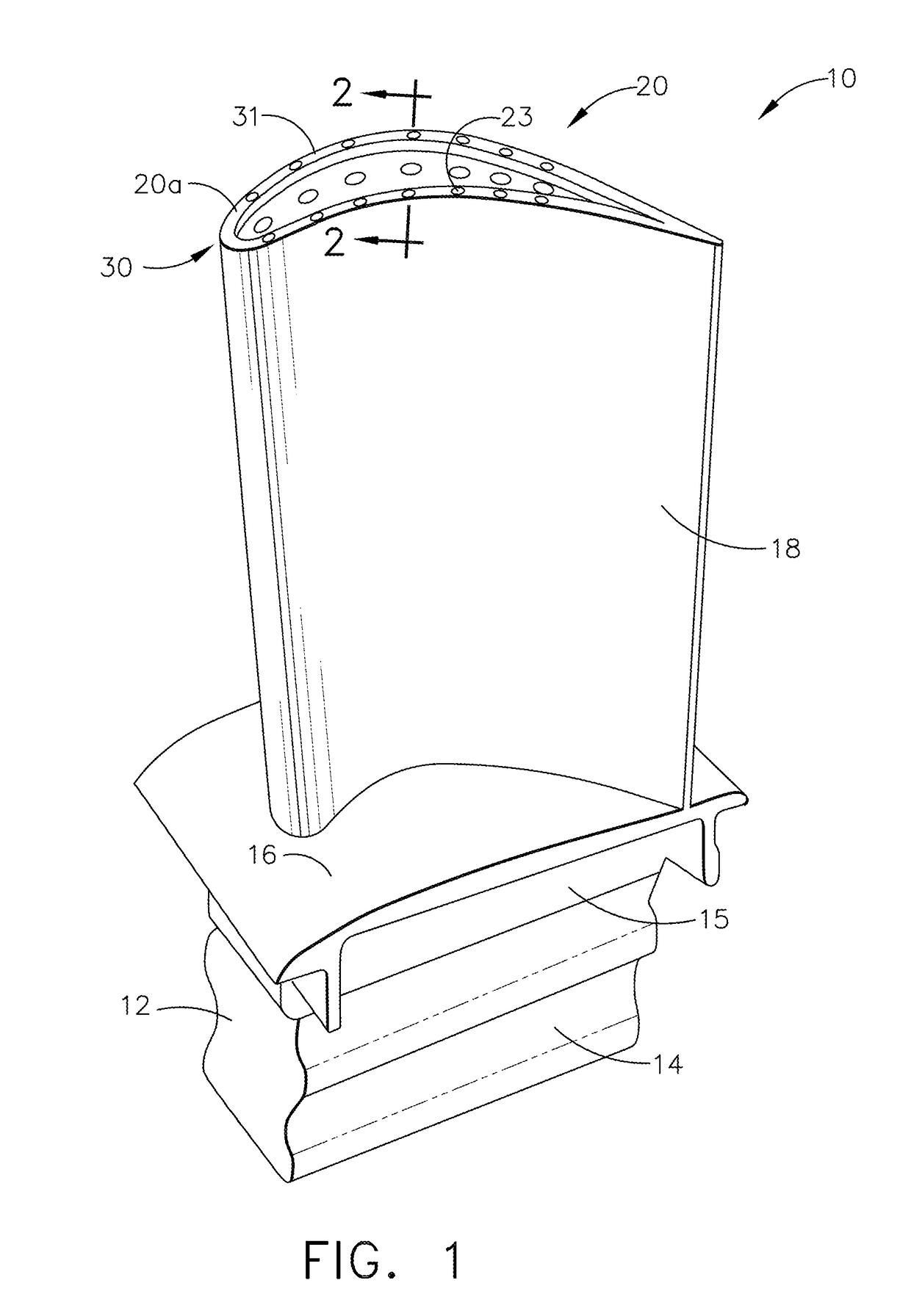
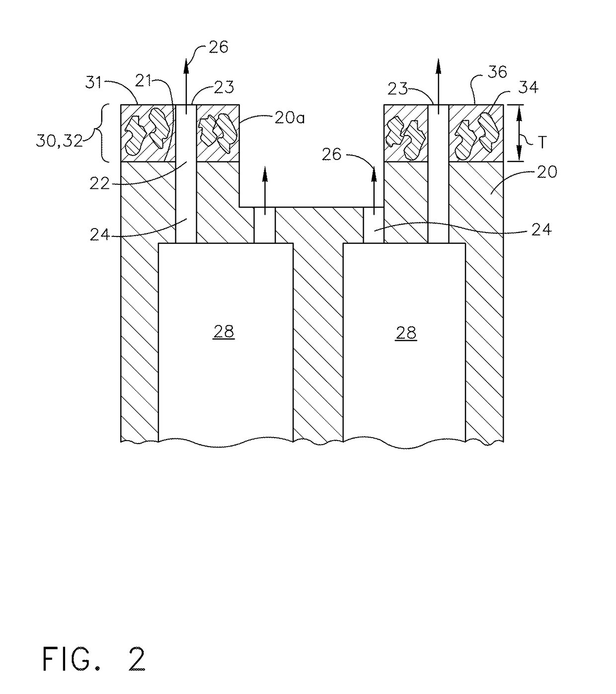
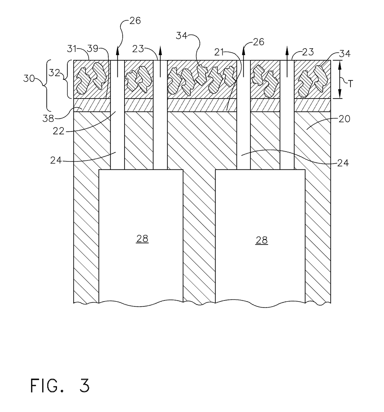
This patent describes a coated turbine blade that reduces wear and rubbing on the blade tip. The blade has a coating system with a plurality of through-holes that connect with a cooling passage in the blade. This coating system helps to protect the blade tip and improve its performance.

Problems solved by technology

During engine operation, the blade tips can sometimes rub against the shroud, thereby increasing the gap and resulting in a loss of efficiency, or in some cases, damaging or destroying the blade set.
In the high environmental temperatures found in an aircraft engine and a gas turbine, the metal blade strength is decreased and the blade-shroud rubbing further elevates the temperature of the blade tip due to friction caused thermal effect, resulting in severe blade wear.
The abradable layer however cannot be too soft, as they will be eroded too fast.
The hardness of this continuous abradable layer may cause it to not abrade, but rather will cause the tips of the rotating blades to abrade.
However, the patterned ridges on the surface of the shroud reduce aerodynamic efficiency and tend to be more expensive and have less thermal protection.

Method used


Image

  • Turbine blade and method of forming blade tip for eliminating turbine blade tip wear in rubbing
  • Turbine blade and method of forming blade tip for eliminating turbine blade tip wear in rubbing
  • Turbine blade and method of forming blade tip for eliminating turbine blade tip wear in rubbing

Examples


Embodiment Construction

[0025]Reference now will be made in detail to embodiments of the invention, one or more examples of which are illustrated in the drawings. Each example is provided by way of explanation of the invention, not limitation of the invention. In fact, it will be apparent to those skilled in the art that various modifications and variations can be made in the present invention without departing from the scope or spirit of the invention. For instance, features illustrated or described as part of one embodiment can be used with another embodiment to yield a still further embodiment. Thus, it is intended that the present invention covers such modifications and variations as come within the scope of the appended claims and their equivalents.

[0026]The terminology used herein is for the purpose of describing particular embodiments only and is not intended to be limiting of the disclosure. As used herein, the singular forms “a”, “an” and “the” are intended to include the plural forms as well, unl...


PUM

PropertyMeasurementUnit
Pressureaaaaaaaaaa
Abrasiveaaaaaaaaaa

Abstract

Coating systems for a cooled turbine blade tip, such as a metal turbine blade tip, are provided. The coating system includes an abrasive layer overlying the surface of the turbine blade tip. One or more buffer layers may additionally be disposed between an outer surface of the blade tip and the abrasive layer. The coated blade tip can be used with a ceramic matrix composite (CMC) shroud coated with an environmental barrier coating (EBC) to provide improved cooling to the tip so as to lengthen oxidation time of the abrasive layer and reduce blade tip wear. Methods are also provided for forming the cooled blade tip and applying the coating system onto the cooled turbine blade tip.

Description

BACKGROUND[0001]The subject matter disclosed herein relates to turbine blade tip wear, and more particularly, a cooled turbine blade including a coating system and methods for eliminating turbine blade tip wear in conjunction with a CMC or metal shroud in a gas turbine engine.[0002]The turbine section of a gas turbine engine contains a rotor shaft and one or more turbine stages, each having a turbine disk (or rotor) mounted or otherwise carried by the shaft and turbine blades mounted to and radially extending from the periphery of the disk. A turbine assembly typically generates rotating shaft power by expanding hot compressed gas produced by combustion of a fuel. Gas turbine buckets or blades generally have an airfoil shape designed to convert the thermal and kinetic energy of the flow path gases into mechanical rotation of the rotor.[0003]Within a turbine engine, a shroud is a ring of material surrounding the rotating blades. Ceramic matrix composites (CMCs) are an attractive mate...

Claims


Application Information

Patent Timeline
IPC IPC(8): F01D11/12F01D5/20F01D5/28F01D5/18
CPCF01D11/122F01D5/20F01D5/28F01D5/18F05D2220/32F05D2240/307F05D2260/2214F05D2300/17F05D2300/2261F05D2300/2262F05D2300/2263F05D2300/2284F05D2300/2283F05D2300/2282F05D2300/2112C23C24/103F01D5/288F01D11/08F01D5/186F01D5/187F05D2240/11F05D2300/6033Y02T50/60
Inventor SHI, JINJIEDRY, DENNIS PAULWOLFE, CHRISTOPHER EDWARDGARCIA-CRESPO, ANDRES JOSEZHU, YUN
Owner GENERAL ELECTRIC CO
Learn More